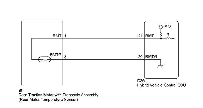
DTC P0A32-666 Drive Motor "B" Temperature Sensor Circuit Low |
DTC P0A33-665 Drive Motor "B" Temperature Sensor Circuit High |
| DTC No. | INF Code | DTC Detection Condition | Trouble Area |
| P0A32 | 666 | GND short in rear motor temperature sensor circuit |
|
| P0A33 | 665 | Open or +B short in rear motor temperature sensor circuit |
| Displayed Temperature | Malfunction |
| -58°F (-50°C) | Open circuit or short to +B |
| 401°F (205°C) | Short to GND |
| 1.CHECK CONNECTOR CONNECTION CONDITION (HYBRID VEHICLE CONTROL ECU CONNECTOR) |
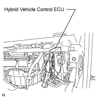 |
Check the connections of all hybrid vehicle control ECU connectors.
|
| ||||
| OK | |
 |
| 2.READ VALUE USING TECHSTREAM (REAR MOTOR TEMP) |
Connect the Techstream to the DLC3.
Turn the power switch on (IG).
Select the following menu items: Powertrain / Hybrid Control / Data List / Rear Motor Temp.
Read the value of "Rear Motor Temp" in the data list displayed on Techstream.
| A | B | C | |
| Rear Motor Temp (°C) | -58°F (-50°C) | 401°F (205°C) | -56.2 to 399.2°F (-49 to 204°C) |
|
| ||||
|
| ||||
| A | |
|
| 3.INSPECT REAR MOTOR TEMPERATURE SENSOR |
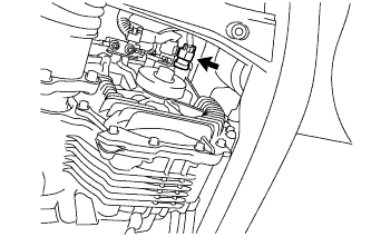 |
Turn the power switch off.
Disconnect the rear motor temperature sensor connector.
Turn the power switch on (IG).
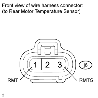 |
Measure the voltage according to the value(s) in the table below.
| Tester Connection | Switch Condition | Voltage | Proceed to |
| j6-1 (RMT) - j6-3 (RMTG) | Power switch on (IG) | Approximately 5 V | A |
| Power switch on (IG) | 11 to 14 V | B | |
| Power switch on (IG) | Approximately 0 V | C |
|
| ||||
|
| ||||
| A | ||
 | ||
| ||
| 4.CHECK HARNESS AND CONNECTOR (HYBRID VEHICLE CONTROL ECU - REAR MOTOR TEMPERATURE SENSOR) |
Turn the power switch off.
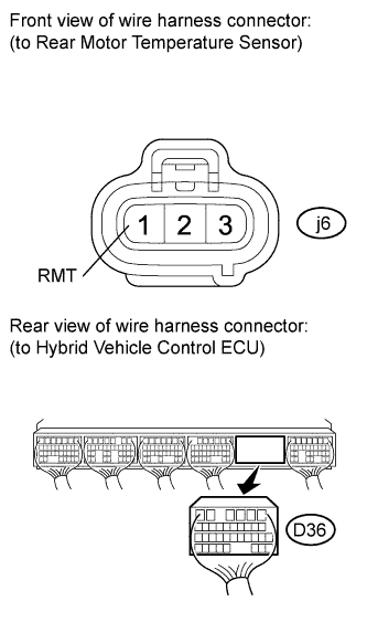 |
Disconnect connector D36 from the hybrid vehicle control ECU.
Turn the power switch on (IG).
Measure the voltage according to the value(s) in the table below.
| Tester Connection | Switch Condition | Specified Condition |
| j6-1 (RMT) - Body ground | Power switch on (IG) | Approximately 0 V |
|
| ||||
| OK | ||
| ||
| ||
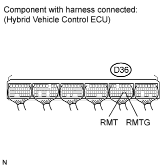
| 5.READ VALUE USING TECHSTREAM (REAR MOTOR TEMP) |
Turn the power switch off.
Connect terminals 21 (RMT) and 20 (RMTG) of connector D36 of the hybrid vehicle control ECU.
Turn the power switch on (IG).
Select the following menu items: Powertrain / Hybrid Control / Data List / Rear Motor Temp.
 |
Read the data list.
| Tester Display | Condition | Specified Condition |
| Rear Motor Temp | Terminals RMT and RMTG connected. Power switch on (IG) | 401°F (205°C) |
|
| ||||
| OK | ||
| ||
| ||
| 6.READ VALUE USING TECHSTREAM (REAR MOTOR TEMP) |
Turn the power switch off.
|
Disconnect the rear motor temperature sensor connector.
Turn the power switch on (IG).
Select the following menu items: Powertrain / Hybrid Control / Data List / Rear Motor Temp.
Read the data list.
| Tester Display | Switch Condition | Specified Condition |
| Rear Motor Temp | Power switch on (IG) | -58°F (-50°C) |
|
| ||||
| OK | ||
| ||
| ||
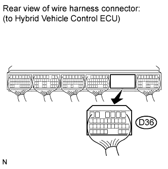
| 7.READ VALUE USING TECHSTREAM (REAR MOTOR TEMP) |
Turn the power switch off.
Disconnect connector D36 from the hybrid vehicle control ECU.
Turn the power switch on (IG).
Select the following menu items: Powertrain / Hybrid Control / Data List / Rear Motor Temp.
 |
Read the data list.
| Tester Display | Switch Condition | Specified Condition |
| Rear Motor Temp | Power Switch on (IG) | -58°F (-50°C) |
|
| ||||
| OK | ||
| ||
| ||

