| B |  |
| GO TO DTC CHART (Click here) |
DTC P3147-239 Transmission Malfunction |
DTC P3147-241 Transmission Malfunction |
DTC P3147-602 Transmission Malfunction |
| DTC No. | INF Code | DTC Detection Condition | Trouble Area |
| P3147 | 239 | Hybrid vehicle transaxle input malfunction (shaft damaged) |
|
| 241 | Hybrid vehicle transaxle input malfunction (input damper system) | ||
| 602 | Transaxle output malfunction |
| 1.CHECK DTC OUTPUT (SFI SYSTEM) |
Connect the Techstream to the DLC3.
Turn the power switch on (IG).
Select the following menu items: Powertrain / Engine Control / Trouble Codes.
Check if DTCs are output.
| Result | Proceed to |
| Engine control system DTCs are not output. | A |
| Engine control system DTCs are output. | B |
|
| ||||
| A | |
 |
| 2.INSPECT CRANKSHAFT PULLEY REVOLUTION (P POSITION) |
Turn the power switch off.
Move the shift lever to the P position, and lift up the vehicle.
Turn the crankshaft pulley using hand tools to check if the crankshaft can rotate smoothly.
| Result | Proceed to |
| The crankshaft rotates smoothly | A |
| The crankshaft does not rotate smoothly | B |
|
| ||||
| A | |
|
| 3.CHECK HARNESS AND CONNECTOR (HYBRID VEHICLE CONTROL ECU - CRANKSHAFT POSITION SENSOR) |
Disconnect connector B3 from the hybrid vehicle control ECU.
Disconnect the B21 crankshaft position sensor connector.
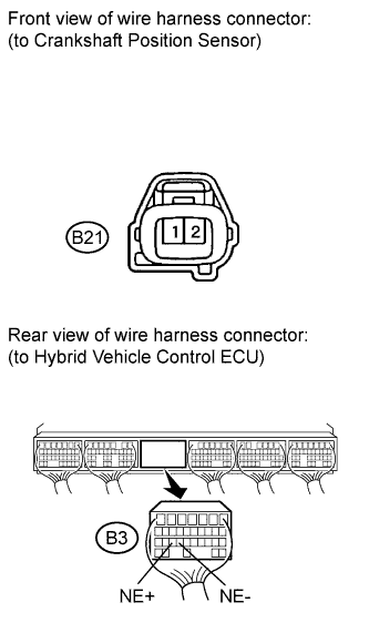 |
Measure the resistance according to the value(s) in the table below.
| Tester Connection | Switch Condition | Specified Condition |
| B3-25 (NE+) - B21-1 (NE+) | Power switch off | Below 1 Ω |
| B3-24 (NE-) - B21-2 (NE-) | Power switch off | Below 1 Ω |
| Tester Connection | Switch Condition | Specified Condition |
| B3-25 (NE+) or B21-1 (NE+) - Body ground and other terminals | Power switch off | 10 kΩ or higher |
| B3-24 (NE-) or B21-2 (NE-) - Body ground and other terminals | Power switch off | 10 kΩ or higher |
|
| ||||
| OK | |
|
| 4.INSPECT CRANKSHAFT POSITION SENSOR |
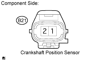 |
Disconnect the crankshaft position sensor connector.
Measure the resistance according to the value(s) in the table below.
| Tester Connection | Condition | Specified Condition |
| B21-1 - B21-2 | Cold | 1630 to 2740 Ω |
| Hot | 2065 to 3225 Ω |
|
| ||||
| OK | |
|
| 5.CHECK DTC OUTPUT (HV) |
Connect the Techstream to the DLC3.
Turn the power switch on (IG).
Select the following menu items: Powertrain / Hybrid Control / Trouble Codes.
Check for hybrid vehicle control system DTCs, freeze frame data, and diagnosis information and note them down.
| NEXT | |
|
| 6.CLEAR DTC (HV) |
Select the following menu items: Powertrain / Hybrid Control / Trouble Codes.
Clear DTCs and freeze frame data.
| NEXT | |
|
| 7.CHECK READY INDICATOR ON |
Connect the Techstream to the DLC3.
Turn the power switch on (IG).
Select the following menu items: Powertrain / Hybrid Control / Data List / Generator (MG1) Rev, Engine Spd.
Turn the power switch on (READY).
|
| ||||
| OK | |
|
| 8.CHECK ENGINE RACING |
Connect the Techstream to the DLC3.
Turn the power switch on (IG).
Select the following menu items: Powertrain / Hybrid Control / Data List / Generator (MG1) Rev, Engine Spd.
While the READY light is on, depress the accelerator pedal for 10 seconds with the shift lever in the P position.
|
| ||||
| OK | |
|
| 9.CHECK CREEP MOVEMENT |
Connect the Techstream to the DLC3.
Depress the brake pedal, move the shift lever to the D position, and release the brake pedal.
|
| ||||
| OK | |
|
| 10.INSPECT ENGINE SPEED |
Connect the Techstream to the DLC3.
While driving at the vehicle speed of more than 6 mph (10 km/h), fully depress the accelerator pedal to raise the engine speed.
|
| ||||
| OK | ||
 | ||
| ||
| 11.INSPECT FRONT TIRE REVOLUTION |
Lift up the vehicle.
Move the shift lever to the N position with the power switch off.
Turn the crank pulley using hand tools to check if the front tires rotate.
|
| ||||
| OK | ||
| ||
| ||
