 |
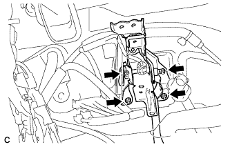
Install the brake master cylinder bracket to the body with the 4 nuts.
- Torque:
- 13 N*m{ 132 kgf*cm , 10 ft.*lbf }
BRAKE MASTER CYLINDER > INSTALLATION |
| 1. INSTALL BRAKE BOOSTER GASKET |
Install a new brake booster gasket to the brake master cylinder gasket.
| 2. INSTALL BRAKE MASTER CYLINDER BRACKET |
|
Install the brake master cylinder bracket to the body with the 4 nuts.
| 3. INSTALL BRAKE MASTER CYLINDER GASKET |
Install a new brake master cylinder gasket to the brake master cylinder bracket.
| 4. INSTALL BRAKE STROKE SIMULATOR CYLINDER SUB-ASSEMBLY |
Install the brake stroke simulator cylinder sub-assembly to the brake master cylinder bracket.
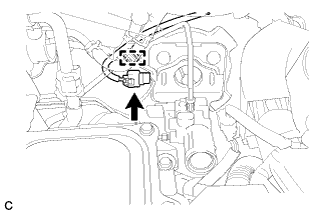 |
Engage the clamp and connect the connector.
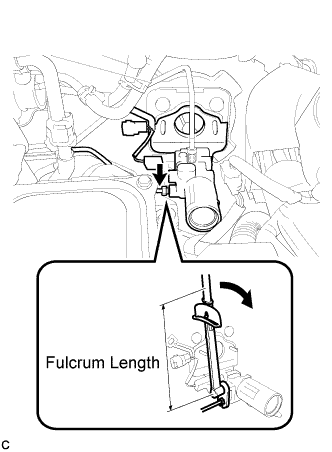 |
Using a union nut wrench (10 mm), connect the brake line to the brake stroke simulator cylinder sub-assembly.
| 5. INSTALL BRAKE MASTER CYLINDER GASKET |
Install a new brake master cylinder gasket to the brake master cylinder sub-assembly.
| 6. INSTALL BRAKE MASTER CYLINDER SUB-ASSEMBLY |
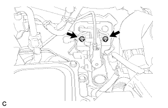 |
Install the brake master cylinder sub-assembly to the brake master cylinder bracket with the 2 nuts.
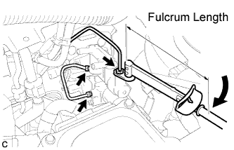 |
Using a union nut wrench (10 mm), install the brake stroke simulator tube and connect the brake lines to the brake master cylinder sub-assembly.
| 7. INSTALL PUSH ROD PIN |
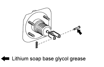 |
Apply lithium soap base glycol grease to the push rod pin.
Install the push rod pin to connect the brake master cylinder push rod clevis and brake pedal sub-assembly as shown in the illustration.
Install a new clip to the push rod pin.
| 8. INSTALL BRAKE PEDAL RETURN SPRING |
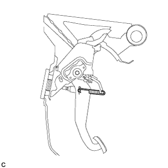 |
Install the brake pedal return spring between the instrument panel reinforcement and brake master cylinder push rod clevis.
| 9. CONNECT NO. 1 RESERVOIR HOSE |
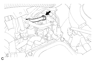 |
Connect the No. 1 reservoir hose to the brake master cylinder sub-assembly with the clips.
| 10. CONNECT NO. 2 RESERVOIR HOSE |
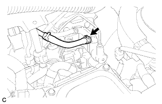 |
Connect the No. 2 reservoir hose to the brake master cylinder sub-assembly with the clips.
| 11. INSTALL WIRE HARNESS |
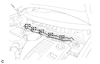 |
Engage the 5 clamps to install the wire harness to the body.
| 12. CONNECT CABLE TO NEGATIVE BATTERY TERMINAL |
| 13. INSTALL SERVICE PLUG GRIP |
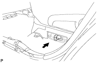 |
Wear insulated gloves, then insert the service plug.
Push down on the grip to lock.
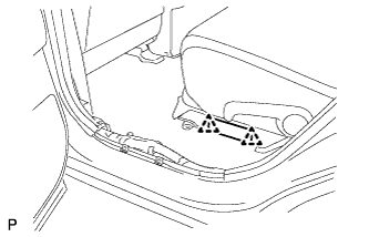 |
Close the reclining hinge cover.
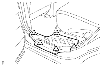 |
Close the rear door scuff plate LH.
| 14. BLEEDING PRECAUTION |
| 15. PERFORM ACCUMULATOR ZERO DOWN |
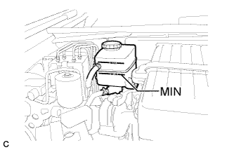 |
Drain the brake fluid in the reservoir tank near the MIN line.
Connect the Techstream to the DLC3 with the power switch off.
Check that the parking brake is set, and turn the power switch on (IG).
Enter the following menus: Chassis / ABS/VSC/TRC / Utility / Electronically Controlled Brake system Utility / Zero Down.
When the buzzer sounds, turn the power switch off.
| 16. FILL RESERVOIR WITH BRAKE FLUID |
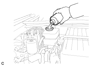 |
Add brake fluid into the reservoir.
| 17. BLEED BRAKE SYSTEM |
Connect the Techstream to the DLC3 with the power switch off.
Check that the parking brake is set, and turn the power switch on (IG).
Enter the following menus: Chassis / ABS/VSC/TRC / Air Bleeding.
Select the menu on the Techstream display based on the following list.
| Select "Usual air bleeding" on the Techstream display. |
| Air bleeding (no part replacement) | Select "Actuator has been removed" on the Techstream display. |
|
|
| Brake master cylinder reservoir (removal, installation or replacement) |
|
|
|
After air bleeding or replacement, tighten the bleeder plug.
| 18. PERFORM ACCUMULATOR ZERO DOWN |
|
Drain the brake fluid in the reservoir tank near the MIN line.
Connect the Techstream to the DLC3 with the power switch off.
Check that the parking brake is set, and turn the power switch on (IG).
Enter the following menus: Chassis / ABS/VSC/TRC / Utility / Electronically Controlled Brake system Utility / Zero Down.
When the buzzer sounds, turn the power switch off.
| 19. INSPECT AND ADJUST BRAKE FLUID LEVEL IN RESERVOIR |
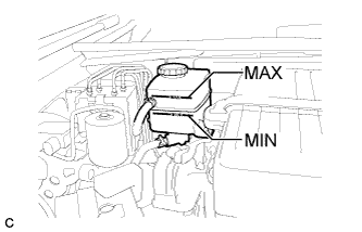 |
Inspect the fluid level. If the brake fluid level is lower than the MIN line, inspect for brake fluid leakage and brake pad. After repair or replacement, adjust the brake fluid level in the reservoir as specified below.
Add the brake fluid to the MAX line with the power switch on (IG).
| 20. INSPECT FOR BRAKE FLUID LEAK |
| 21. ADJUST BRAKE PEDAL HEIGHT |
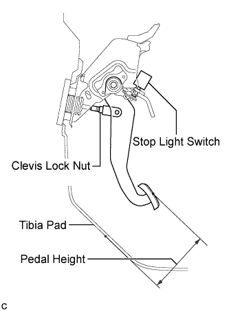
Check the brake pedal height.
 |
Turn back the carpet.
Measure the shortest distance between the brake pedal surface and tibia pad.
Adjust the brake pedal height.
Disconnect the stop light switch connector.
Remove the stop light switch assembly.
Loosen the push rod clevis lock nut.
Adjust the brake pedal height by turning the push rod.
Tighten the push rod clevis lock nut.
Install and adjust the stop light switch .
Connect the stop light switch connector.
| 22. ADJUST BRAKE PEDAL STROKE SENSOR ASSEMBLY |
When installing a new brake pedal stroke sensor assembly:
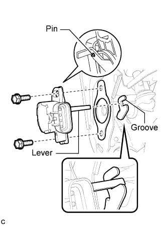 |
Connect the sensor connector.
Install a new sensor with the 2 bolts.
Firmly depress the brake pedal and break the sensor lever set pin.
Remove the broken lever set pin.
When reusing the brake pedal stroke sensor assembly:
Connect the sensor connector.
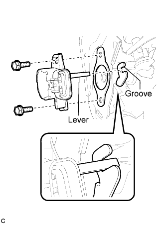 |
Temporarily install the sensor with the 2 bolts.
Connect the cable to the negative battery terminal.
Connect the Techstream to the DLC3.
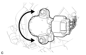 |
Turn the power switch on (IG). Reading the value of the stroke sensor shown in Data List, turn the sensor slowly to the right and left to adjust the output voltage to the standard voltage.
| Tester Display | Measurement Item/Range | Normal Condition | Diagnostic Note |
| Stroke Sensor | Stroke sensor / min.: 0 V, max.: 5 V | When brake pedal is released: 0.7 to 1.3 V | - |
Tighten the 2 bolts.
Disconnect the cable from the negative battery terminal.
Disconnect the Techstream.
| 23. ADJUST BRAKE PEDAL FREE PLAY |
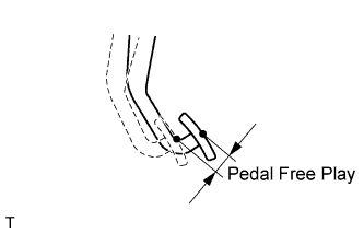 |
Depress the pedal until a slight resistance is felt. Measure the distance as shown in the illustration.
| 24. ADJUST BRAKE PEDAL RESERVE DISTANCE |
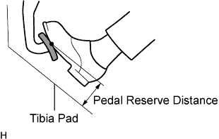 |
Release the parking brake lever.
With the engine running, depress the brake pedal and measure the pedal reserve distance as shown in the illustration.
| 25. CHECK AND CLEAR DTC |
Check and clear the DTCs (Click here).
| 26. CHECK BRAKE MASTER CYLINDER WITH TESTER |
Check the brake master cylinder and stroke simulator (Click here).
| 27. CHECK MASTER CYLINDER PRESSURE SENSOR SIGNAL |
Check the pressure sensor signal (Click here).
| 28. CHECK FOR DTC |
Check for DTCs. If any DTC is output, perform the troubleshooting for that DTC (Click here).
| 29. INSTALL OUTER COWL TOP PANEL SUB-ASSEMBLY |
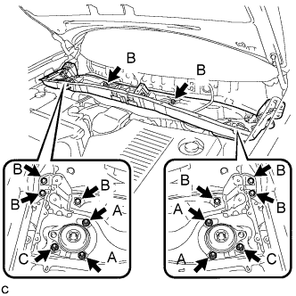 |
Install the outer cowl top panel sub-assembly with the 8 bolts and 6 nuts.
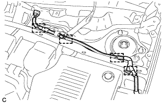 |
Engage the 4 clamps.
| 30. INSTALL WINDSHIELD WIPER MOTOR AND LINK |
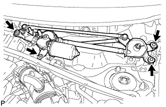 |
Install the windshield wiper motor and link assembly with the 4 bolts.
Connect the connector.
| 31. INSTALL COWL TOP VENTILATOR LOUVER SUB-ASSEMBLY |
Engage the 20 claws.
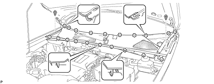
Install the cowl top ventilator louver sub-assembly with the 2 clips.
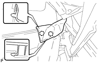 |
Engage the 2 claws and connect the front fender to cowl side seal LH.
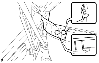 |
Engage the 2 claws and connect the front fender to cowl side seal RH.
| 32. INSTALL FRONT WIPER ARM AND BLADE ASSEMBLY RH |
Operate the wiper and stop the windshield wiper motor at the automatic stop position.
When reinstalling:
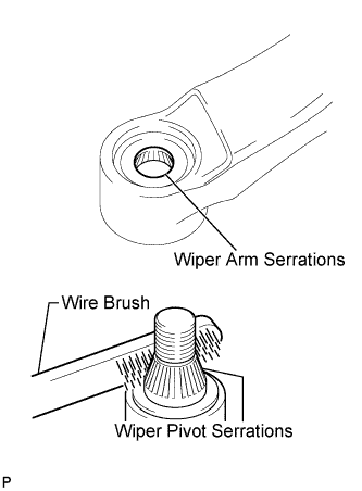 |
Clean the wiper arm serrations.
Clean the wiper pivot serrations with a wire brush.
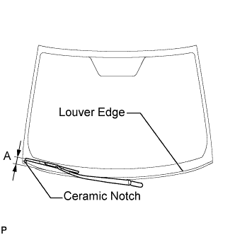 |
Install the front wiper arm and blade assembly RH with the nut to the position shown in the illustration.
| Area | Measurement |
| A | 25.6 mm (1.00 in.) |
| 33. INSTALL FRONT WIPER ARM AND BLADE ASSEMBLY LH |
Operate the wiper and stop the windshield wiper motor at the automatic stop position.
When reinstalling:
|
Clean the wiper arm serrations.
Clean the wiper pivot serrations with a wire brush.
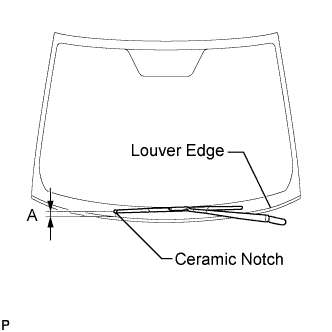 |
Install the front wiper arm and blade assembly LH with the nut to the position shown in the illustration.
| Area | Measurement |
| A | 31.9 mm (1.26 in.) |
Operate the front wipers while spraying washer fluid onto the windshield glass. Make sure that the front wipers function properly and the wipers do not come into contact with the vehicle body.