Home › BRAKE › BRAKE CONTROL › BRAKE ACTUATOR

BRAKE ACTUATOR > INSTALLATION

for Preparation Click here


NOTICE:
While the battery is connected, even if the power switch is off, the brake control system activates when the brake pedal is depressed or any door courtesy switch turns on. Therefor, when servicing the brake system components, do not operate the brake pedal or open/close the doors while the battery is connected.


1. INSTALL NO. 2 BRAKE ACTUATOR HOSE

NOTICE:
When inserting the hose, be careful that there is no excessive weight applied to the union of the brake accumulator (especially in the union rotation direction).


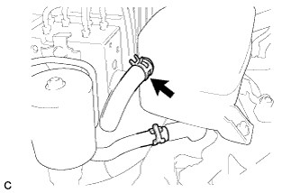
    C171422
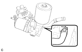
  1. Install the No. 2 brake actuator hose with the clip.


2. INSTALL BRAKE BOOSTER PUMP


    C171421
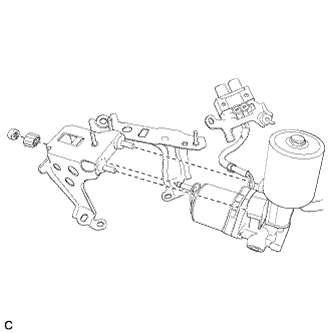
  1. Install the brake booster pump to the brake actuator bracket.


    C171420E01
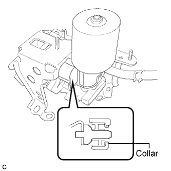
  1. Check for the brake booster pump collar.
    NOTICE:
    After installing the brake booster pump, make sure the collar has not fallen off.


    C171419E01
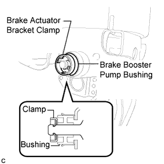
  1. Install the brake booster pump bush and a new brake actuator bracket clamp to the brake booster pump.

    NOTICE:
    Make sure to securely insert the brake booster pump until the claws of the clamp are engaged.


3. INSTALL BRAKE ACTUATOR

NOTICE:
Do not remove the hole plugs before installing a new brake actuator because the brake actuator is filled with brake fluid.


    C171415E01
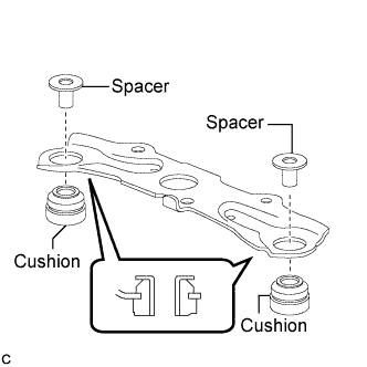
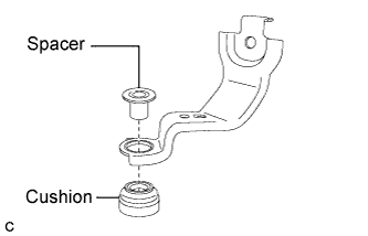
  1. Install the 2 cushions and 2 spacers to the No. 1 brake actuator bracket.


    C171414E02
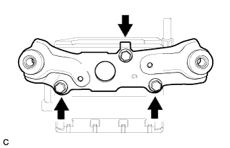
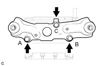
  1. Temporally install the No. 1 brake actuator bracket to the brake actuator with the bolt A and bolt B.

  1. Install the bolt C.


    C171414E01
  1. Fully tighten the No. 1 brake actuator bracket to the brake actuator with the 3 bolts.
    Torque:
    9.3 N*m{ 95 kgf*cm , 82 in.*lbf }


    C171413E01
  1. Install the cushion and spacer to the No. 2 brake actuator bracket.
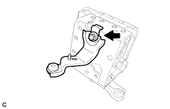


    C171412E01
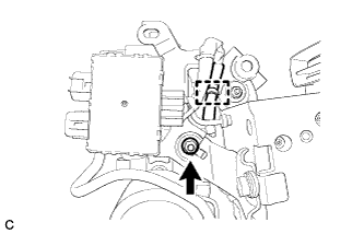
  1. Install the No. 2 brake actuator bracket to the brake actuator with the bolt.
    Torque:
    19 N*m{ 194 kgf*cm , 14 ft.*lbf }


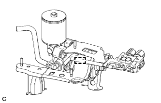
    C171418E01
  1. Install the the brake booster pump clamp.


    C171416
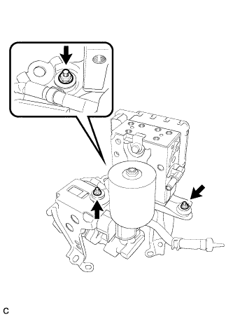
  1. Install the brake actuator with brackets to the brake actuator bracket with the 3 nuts.

    Torque:
    8.0 N*m{ 82 kgf*cm , 71 in.*lbf }


4. INSTALL NO. 3 BRAKE ACTUATOR TUBE

NOTICE:
  1. Do not damage the No. 3 brake actuator tube, brake actuator or brake booster pump.
  2. When installing the No. 3 brake actuator tube, hold the tube, brake actuator and brake booster pump securely.
  3. When tightening the nut, make sure that other parts do not move with the nut.


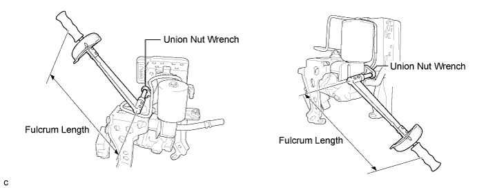
  1. Using a union nut wrench, connect the No. 3 brake actuator tube.

    C171407E01

    Torque:
    without a union nut wrench:
    15 N*m{ 155 kgf*cm , 11 ft.*lbf }
    with a union nut wrench:
    14 N*m{ 143 kgf*cm , 10 ft.*lbf }

    NOTICE:
    1. Use a torque wrench with a fulcrum length of 250 mm (9.84 in.).
    2. The torque value for use with a union nut wrench is effective when the union nut wrench is parallel to the torque wrench.


5. CONNECT BRAKE BOOSTER PUMP CONNECTOR


    C171411
  1. Connect the brake booster pump connector.

    1. Install the brake booster pump connector with the nut.

      Torque:
      8.0 N*m{ 82 kgf*cm , 71 in.*lbf }

    2. Attach the wiring harness clamp.


6. INSTALL NO. 1 BRAKE ACTUATOR HOSE


    C171410
  1. With the paint mark on the hose end facing downward, install the No. 1 brake actuator hose to the brake actuator with the hose clip.

    NOTICE:
    When inserting the hose, be careful that there is no excessive weight applied to the union of the brake actuator (especially in the union rotation direction).


7. INSTALL BRAKE ACTUATOR AND BRAKE BOOSTER PUMP


    C171406
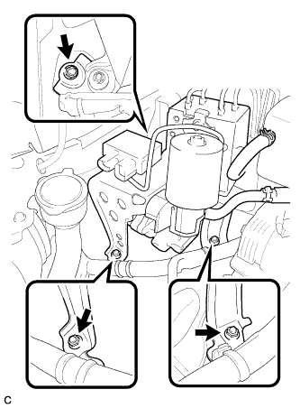
  1. Install the brake actuator and brake booster pump to the body with the 3 nuts.

    NOTICE:
    1. Do not damage the brake tubes.
    2. When installing the brake actuator and brake booster pump to the vehicle, do not hold it by the connectors, harnesses, hoses or tubes parts.
    3. Do not drop the brake actuator or brake booster pump. Do not use parts that have been dropped.

    Torque:
    19 N*m{ 194 kgf*cm , 14 ft.*lbf }


8. CONNECT BRAKE TUBE


    C171405E01
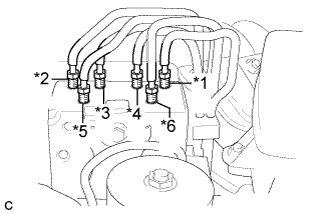
  1. Set each brake tube to the correct positions on the brake actuator as shown in the illustration.
    HINT:
    1. *1: To front wheel cylinder RH
    2. *2: To front wheel cylinder LH
    3. *3: To rear wheel cylinder RH
    4. *4: To rear wheel cylinder LH
    5. *5: From stroke simulator
    6. *6: From master cylinder


    C171409E01
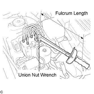
  1. Using a union nut wrench, connect the 6 brake tubes.
    Torque:
    without a union nut wrench:
    15 N*m{ 155 kgf*cm , 11 ft.*lbf }
    with a union nut wrench:
    14 N*m{ 143 kgf*cm , 10 ft.*lbf }

    NOTICE:
    1. Use a torque wrench with a fulcrum length of 250 mm (9.84 in.).
    2. The torque value for use with a union nut wrench is effective when the union nut wrench is parallel to the torque wrench.


    C171400
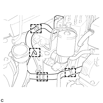
  1. Install the 4 clamps.


    C171403E01
  1. Connect the brake actuator connector.

    NOTICE:
    1. Before connecting the vehicle wire harnesses, make sure that the connector faces are free of foreign matter.
    2. Make sure that the connector is locked securely.


    C170592
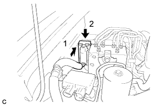
  1. Connect the 2 brake booster pump connectors.

    NOTICE:
    1. Before connecting the vehicle wire harnesses, make sure that the connector faces are free of foreign matter.
    2. Make sure that the connectors are locked securely.


9. INSTALL FRONT WHEEL

Torque:
103 N*m{ 1050 kgf*cm , 76 ft.*lbf }


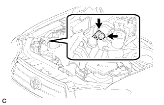
10. INSTALL NO. 1 RESERVOIR HOSE


    C171401E01
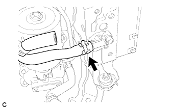
  1. Install the No. 1 reservoir hose.


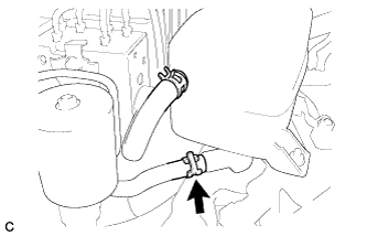
11. INSTALL NO. 2 BRAKE ACTUATOR HOSE


    C171401E02
  1. Install the No. 2 brake actuator hose.


12. INSTALL BATTERY
  1. Install the battery clamp and battery.

    Torque:
    5.4 N*m{ 55 kgf*cm , 48 in.*lbf }

  1. Connect the cable to the battery terminal.

    Torque:
    6.4 N*m{ 65 kgf*cm , 56 in.*lbf }

    NOTICE:
    When disconnecting the cable, some systems need to be initialized after the cable is reconnected (Click here).


13. INSTALL SERVICE PLUG GRIP

NOTICE:
Before connecting the service plug, check that no parts and tools remain and that the high voltage terminals and connectors are connected securely.


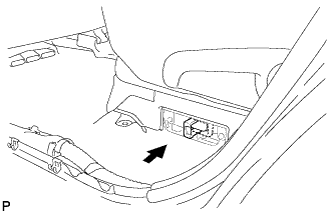
    A176049
  1. Wear insulated gloves, then insert the service plug.

  1. Push down on the grip to lock.


    A175635
  1. Close the reclining hinge cover.

    NOTICE:
    Check that the 2 clips are securely connected to the battery carrier bracket (click sound).


    A175634
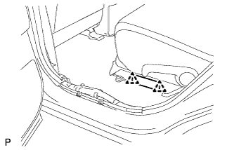
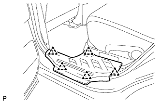
  1. Close the rear door scuff plate LH.

    NOTICE:
    Check that the 5 clips are securely connected to the battery carrier bracket (click sound).


14. CONNECT CABLE TO NEGATIVE BATTERY TERMINAL

NOTICE:
When disconnecting the cable, some systems need to be initialized after the cable is reconnected (Click here).


15. BLEEDING PRECAUTION

CAUTION:
Be sure to read "PRECAUTION" thoroughly before bleeding (Click here).


16. PERFORM ACCUMULATOR PRESSURE ZERO DOWN

HINT:
Using the Techstream to perform accumulator zero down causes the pressurized fluid in the actuator's accumulator to be returned to the brake fluid reservoir.


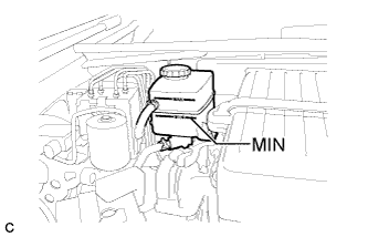
    C170593E03
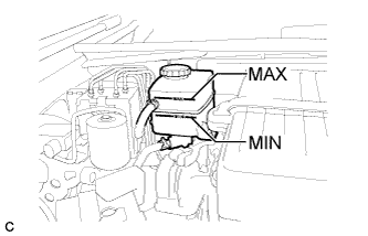
  1. Drain the brake fluid in the reservoir tank near the MIN line.

  1. Connect the Techstream to the DLC3 with the power switch off.

  1. Check that the parking brake is set, and turn the power switch on (IG).

  1. Enter the following menus: Chassis / ABS/VSC/TRC / Utility / Electronically Controlled Brake system Utility / Zero Down.

  1. When the buzzer sounds, turn the power switch off.


17. FILL RESERVOIR WITH BRAKE FLUID

NOTICE:
  1. As brake fluid may overflow when bleeding air, do not place the fluid can on the reservoir filler opening.
  2. If brake fluid leaks onto any painted surface, clean it off completely.


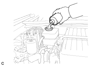
    C170594
  1. Add brake fluid into the reservoir.

    Fluid:
    SAE J1703 or FMVSS No. 116 DOT 3


18. BLEED BRAKE SYSTEM

CAUTION:
The Techstream must be used during fluid replacement. If not used, the fluid replacement will be incomplete, which is hazardous and may lead to an accident.

NOTICE:
  1. Perform fluid replacement while maintaining the brake fluid level between the MIN/MAX level on the brake fluid reservoir.
  2. As brake fluid may overflow, do not place the fluid can on the reservoir filler opening.

  1. Connect the Techstream to the DLC3 with the power switch off.

  1. Check that the parking brake is set, and turn the power switch on (IG).

  1. Enter the following menus: Chassis / ABS/VSC/TRC / Air Bleeding.

  1. Select the menu on the Techstream display based on the following list.

    Bleeding work list 
    1. Brake fluid (replacement)
    2. Front disc brake cylinder (removal, installation or replacement)
    3. Front brake flexible hose (removal, installation or replacement)
    4. Rear disc brake cylinder (removal, installation or replacement)
    5. Rear brake flexible hose (removal, installation or replacement)
    Select "Usual air bleeding" on the Techstream display.
    Air bleeding (no part replacement)
    Select "Actuator has been removed" on the Techstream display.
    1. Brake master cylinder (removal, installation or replacement)
    2. Stroke Simulator (removal, installation or replacement)
    1. Work to be performed before replacement
      1. Using the Techstream, perform accumulator zero down.
      2. Disconnect the 2 brake booster pump connectors.
    2. Select "Master Cylinder or Stroke Simulator has been removed" on the Techstream display.
    Brake master cylinder reservoir (removal, installation or replacement)
    1. Work to be performed before replacement
      1. Using the Techstream, perform accumulator zero down.
      2. Disconnect the 2 brake booster pump connectors.
    2. Work to be performed before air bleeding
      1. Using the Techstream, perform accumulator zero down.
    3. Select "Master Cylinder or Stroke Simulator has been removed" on the Techstream display.
    1. Brake actuator (removal, installation or replacement)
    2. Brake booster pump (removal, installation or replacement)
    1. Work to be performed before replacement
      1. Using the Techstream, perform accumulator zero down.
      2. Disconnect the 2 brake booster pump connectors.
    2. Work to be performed before air bleeding
      1. Using the Techstream, perform accumulator zero down.
    3. Select "Actuator has been removed" on the Techstream display.

  1. After air bleeding or replacement, tighten the bleeder plug.

    Torque:
    8.3 N*m{ 85 kgf*cm , 73 in.*lbf }


19. PERFORM ACCUMULATOR PRESSURE ZERO DOWN

HINT:
Using the Techstream to perform accumulator zero down causes the pressurized fluid in the actuator's accumulator to be returned to the brake fluid reservoir.


    C170593E03
  1. Drain the brake fluid in the reservoir tank near the MIN line.

  1. Connect the Techstream to the DLC3 with the power switch off.

  1. Check that the parking brake is set, and turn the power switch on (IG).

  1. Enter the following menus: Chassis / ABS/VSC/TRC / Utility / Electronically Controlled Brake system Utility / Zero Down.

  1. When the buzzer sounds, turn the power switch off.


20. INSPECT AND ADJUST BRAKE FLUID LEVEL IN RESERVOIR


    C170593E01
  1. Inspect the fluid level. If the brake fluid level is lower than the MIN line, inspect for brake fluid leakage and brake pad. After repair or replacement, adjust the brake fluid level in the reservoir as specified below.

    Brake fluid:
    SAE J1703 or FMVSS No. 116 DOT 3

    NOTICE:
    If using a dropper to adjust the fluid amount, make sure the dropper has not been used with mineral oils, water or deteriorated brake fluid. Sealed areas may deteriorate and lead to fluid leaks, or the fluid may deteriorate and lead to decreased efficiency.


    1. Add the brake fluid to the MAX line with the power switch on (IG).

      NOTICE:
      The brake fluid level must always be adjusted to the MAX line.


21. INSPECT FOR BRAKE FLUID LEAK


22. PERFORM LINEAR VALVE OFFSET LEARNING
  1. When the brake actuator is replaced, perform linear valve offset learning (Click here).


23. CHECK BRAKE ACTUATOR WITH TECHSTREAM

HINT:
(Click here)


24. CHECK FOR DTC
  1. Check for DTCs. If any DTC is output, perform the troubleshooting for that DTC (Click here).