Home › HYBRID SYSTEM · P310 › HYBRID VEHICLE CONTROL › HYBRID CONTROL SYSTEM

DTC    P2601-780    Coolant Pump Control Circuit Range / Performance

for Preparation Click here


DESCRIPTION

HINT:
Although the DTC title refers to "coolant pump", this DTC is related to the oil pump control circuit.

Refer to the description for DTC P2601-777 .

DTC No.
INF No.
DTC Detection Condition
Trouble Area
P2601
780
OPST signal is input even though OPM2 signal is not output
  1. Wire harness or connector
  2. Oil pump with motor assembly
  3. OIL PMP relay
  4. Hybrid vehicle control ECU

WIRING DIAGRAM

Refer to the wiring diagrams for DTC P2601-777 and DTC P3110-139 .

INSPECTION PROCEDURE

NOTICE:
  1. When troubleshooting the oil pump with motor assembly, check for the following conditions:
    1. ATF temperature inside the oil cooler is 41°F (5°C) or more.
    2. The ambient temperature sensor value is 41°F (5°C) or more.

1.CHECK OIL PMP RELAY
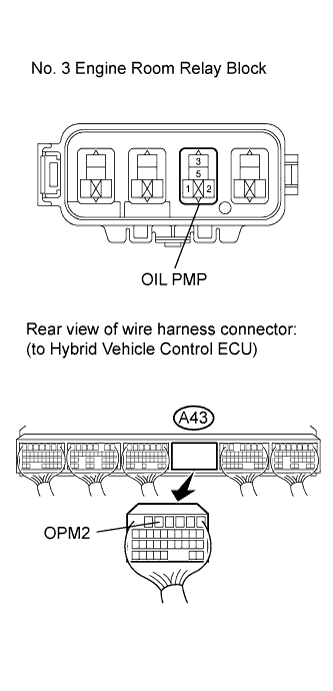
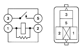
  1. Remove the OIL PMP relay from the No. 3 engine room relay block.


    B016200E02
  1. Measure the resistance according to the value(s) in the table below.

    Standard resistance:
    Tester Connection
    Condition
    Specified Condition
    1 - 2
    Always
    130 to 235 Ω
    3 - 5
    Auxiliary battery voltage is not applied between terminals 1 and 2
    10 kΩ or higher
    Auxiliary battery voltage is applied between terminals 1 and 2
    Below 1 Ω


NG
REPLACE OIL PMP RELAY
OK


2.CHECK HARNESS AND CONNECTOR (HYBRID VEHICLE CONTROL ECU - OIL PMP RELAY)
  1. Remove the OIL PMP relay from the No.3 engine room relay block.

  1. Disconnect connector A43 from hybrid vehicle control ECU.

  1. Turn the power switch on (IG).


    A175446E05
  1. Measure the voltage according to the value(s) in the table below.

    Standard voltage:
    Tester Connection
    Switch Condition
    Specified Condition
    A43-5 (OPM2) - Body ground
    Power switch on (IG)
    Below 1 V

    NOTICE:
    Turning the power switch on (IG) with the hybrid vehicle control ECU connectors disconnected causes other DTCs to be stored. Clear the DTCs after performing this inspection.

  1. Turn the power switch off.

  1. Measure the resistance according to the value(s) in the table below.

    Standard resistance (Check for open):
    Tester Connection
    Switch Condition
    Specified Condition
    A43-5 (OPM2) - No. 3 engine room relay block OIL PMP relay terminal 1
    Power switch off
    Below 1 Ω

    Standard resistance (Check for short):
    Tester Connection
    Switch Condition
    Specified Condition
    A43-5 (OPM2) or No. 3 engine room relay block OIL PMP relay terminal 1 - Body ground and other terminals
    Power switch off
    10 kΩ or higher


NG
REPAIR OR REPLACE HARNESS OR CONNECTOR
OK


3.CHECK HYBRID VEHICLE CONTROL ECU
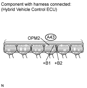
  1. Connect connector A43 to the hybrid vehicle control ECU.


    A174222E26
  1. Measure the resistance according to the value(s) in the table below.

    Standard resistance:
    Tester Connection
    Switch Condition
    Specified Condition
    A43-5 (OPM2) - A43-2 (+B1) and A43-1 (+B2)
    Power switch off
    10 kΩ or higher


NG
REPLACE HYBRID VEHICLE CONTROL ECU (Click here)
OK


4.PERFORM SIMULATION TEST
  1. Connect the Techstream to the DLC3.

  1. Turn the power switch on (IG).

  1. Select the following menu items: Powertrain / Hybrid Control / Active Test / Inspection Mode -2WD Inspection.

  1. Turn the power switch on (READY) and turn on the oil pump relay (activate the oil pump with motor assembly).

  1. Exit "Inspection Mode -2WD Inspection" and turn the power switch off.

  1. Repeat the above four steps to turn the oil pump relay on and off.

    Result:
    Result
    Proceed to
    DTC P2601-780 is output. (The symptom is reproduced.)
    A
    DTC P2601-780 is not output. (The symptom is not reproduced.)
    B


B
CHECK FOR INTERMITTENT PROBLEM (Click here)
A

REPLACE OIL PUMP WITH MOTOR ASSEMBLY (Click here)