 |
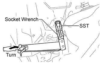
Using SST and a socket wrench (21 mm), install the stud bolt.
- SST
- 09817-33190
- Torque:
- 180 N*m{ 1840 kgf*cm , 133 ft.*lbf }
REAR SUSPENSION MEMBER > INSTALLATION |
| 1. INSTALL STUD BOLT (for LH Side) |
|
Using SST and a socket wrench (21 mm), install the stud bolt.
| 2. INSTALL STUD BOLT (for RH Side) |
| 3. TEMPORARILY INSTALL REAR NO. 2 BODY MOUNTING BRACKET SUB-ASSEMBLY LH |
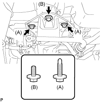 |
Temporarily install the rear No. 2 body mounting bracket sub-assembly LH with the 2 bolts (A) and bolt (B).
| 4. TEMPORARILY INSTALL REAR NO. 2 BODY MOUNTING BRACKET SUB-ASSEMBLY RH |
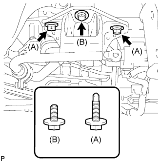 |
Temporarily install the rear No. 2 body mounting bracket sub-assembly RH with the 2 bolts (A) and bolt (B).
| 5. INSTALL HOLE PLUG |
Install the 2 hole plugs.
| 6. INSTALL DIFFERENTIAL MOUNT CUSHION |
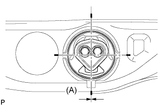 |
Temporarily install a new differential mount cushion front cushion while confirming the installation direction.
Install SST to rear suspension member as shown in the illustration.
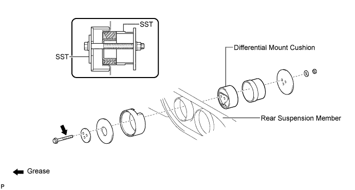
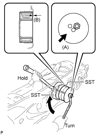 |
While tapping the area around the tip of arrow (A) in the illustration using a hammer, use SST to install the differential mount cushion.
| 7. INSTALL REAR SUSPENSION MEMBER BODY MOUNTING FRONT CUSHION (for LH Side) |
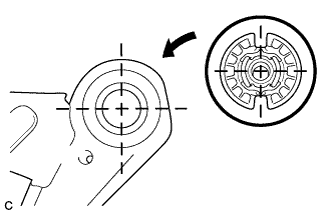 |
Temporarily install a new rear suspension member body mounting front cushion while confirming the installation direction.
Using SST, install the rear suspension member body mounting front cushion until there is no clearance between the suspension member sub- assembly and the rear suspension member body mounting front cushion.
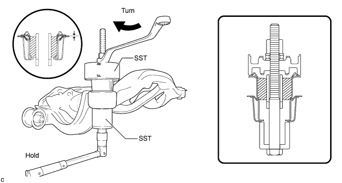
| 8. INSTALL REAR SUSPENSION MEMBER BODY MOUNTING FRONT CUSHION (for RH Side) |
| 9. INSTALL REAR SUSPENSION MEMBER BODY MOUNTING REAR CUSHION (for LH Side) |
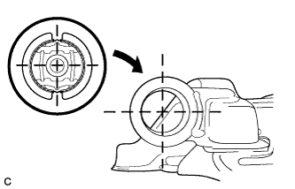 |
Temporarily install a new rear suspension member body mounting rear cushion while confirming the installation direction.
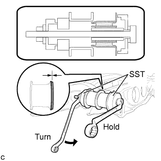 |
Using SST, install the rear suspension member rear body mounting cushion until there is no clearance between the suspension member sub-assembly and the rear suspension member body mounting rear cushion.
| 10. INSTALL REAR SUSPENSION MEMBER BODY MOUNTING REAR CUSHION (for RH Side) |
| 11. INSTALL REAR TRACTION WITH TRANSAXLE MOTOR ASSEMBLY |
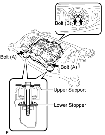 |
Temporarily install the rear traction with transaxle motor assembly (front side) with the 2 lower stoppers, 2 upper supports, and 2 new bolts (A) as shown in the illustration.
Temporarily install the rear traction with transaxle motor assembly (rear side) with the 2 new bolts (B).
Fully tighten the 2 bolts (A).
Fully tighten the 2 bolts (B).
| 12. TEMPORARILY INSTALL REAR SUSPENSION MEMBER |
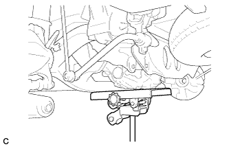 |
Raise the rear suspension member with a jack.
Temporarily install the rear suspension member, the 2 rear upper suspension member stoppers and rear lower suspension member stopper retainers with the 4 nuts and the 2 bolts.
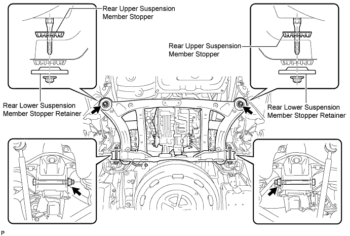
Fully tighten the 2 nuts.
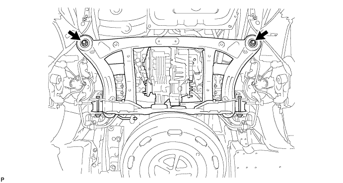
| 13. FULLY TIGHTEN REAR NO. 2 BODY MOUNTING BRACKET SUB-ASSEMBLY LH |
Lightly shake the rear suspension member to settle the body mounting cushion in the rear No. 2 body mounting bracket sub-assembly.
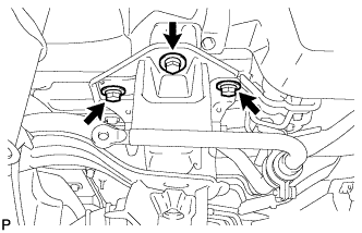 |
Fully tighten the 3 bolts.
| 14. FULLY TIGHTEN REAR NO. 2 BODY MOUNTING BRACKET SUB-ASSEMBLY RH |
Lightly shake the rear suspension member to settle the body mounting cushion in the rear No. 2 body mounting bracket sub-assembly.
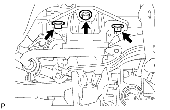 |
Fully tighten the 3 bolts.
| 15. FULLY TIGHTEN REAR SUSPENSION MEMBER |
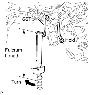 |
Using SST and a socket wrench (19 mm), fully tighten the nut (LH side).
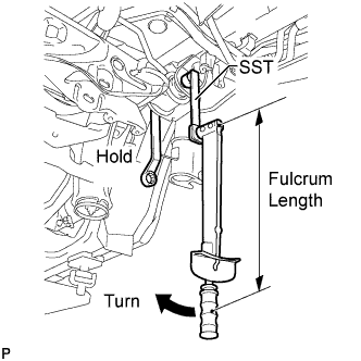 |
Using SST and a socket wrench (19 mm), fully tighten the nut (RH side).
| 16. INSTALL NO. 3 WIRE FRAME |
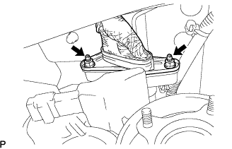 |
Wear insulated gloves. Install the No. 3 frame wire to the rear traction motor with the 2 nuts.
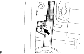 |
Install the wire harness clamp to the vehicle with the nut.
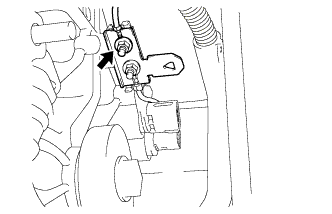 |
Install the ground cable to the rear traction motor with the nut.
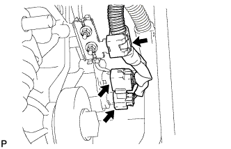 |
Connect the 2 connectors and clamp to the rear traction motor.
| 17. INSTALL REAR DRIVE SHAFT ASSEMBLY LH |
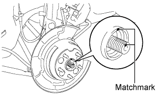 |
Align the matchmarks on the rear drive shaft assembly LH and rear axle hub LH.
Insert the rear drive shaft assembly to the rear axle hub LH.
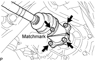 |
Align the matchmarks on the rear drive shaft assembly LH and the differential side gear shaft LH.
Install the rear drive shaft assembly with the 4 nuts and washers.
| 18. INSTALL REAR DRIVE SHAFT ASSEMBLY RH |
| 19. TEMPORARILY INSTALL REAR NO. 1 SUSPENSION ARM ASSEMBLY LH |
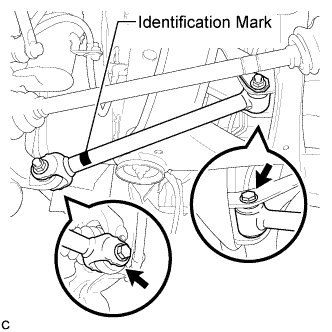 |
Temporarily install the rear No. 1 suspension arm assembly with the 2 bolts and the 2 nuts.
| 20. TEMPORARILY INSTALL REAR NO. 1 SUSPENSION ARM ASSEMBLY RH |
| 21. TEMPORARILY INSTALL REAR NO. 2 SUSPENSION ARM ASSEMBLY LH |
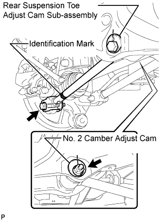 |
Temporarily install the rear No. 2 suspension arm assembly to the rear suspension member sub-assembly with the rear suspension toe adjust cam sub-assembly, the No. 2 camber adjust cam and the nut.
Temporarily install the rear No. 2 suspension arm assembly to the rear axle carrier sub-assembly with the bolt and the nut.
| 22. TEMPORARILY INSTALL REAR NO. 2 SUSPENSION ARM ASSEMBLY RH |
| 23. TEMPORARILY INSTALL REAR STRUT ROD ASSEMBLY LH |
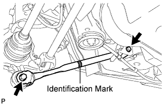 |
Check that the identification mark of the rear strut rod assembly is positioned on the inner side of the vehicle.
Temporarily install the rear strut rod assembly with the 2 bolts and the 2 nuts.
| 24. TEMPORARILY INSTALL REAR STRUT ROD ASSEMBLY RH |
| 25. INSTALL REAR AXLE SHAFT NUT LH |
Clean the threaded parts on the drive shaft and axle hub nut using a non-residue solvent.
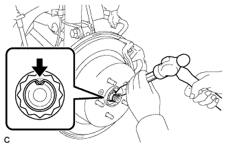 |
Install a new rear axle shaft nut.
Using a chisel and hammer, stake the rear axle shaft nut.
| 26. INSTALL REAR AXLE SHAFT NUT RH |
| 27. STABILIZE SUSPENSION |
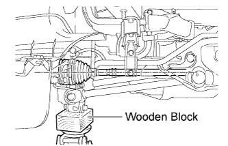 |
Jack up the rear axle carrier sub-assembly, placing a wooden block underneath to avoid damage. Apply load to the suspension so that the rear drive shaft assembly is positioned horizontally.
| 28. FULLY TIGHTEN REAR NO. 1 SUSPENSION ARM ASSEMBLY LH |
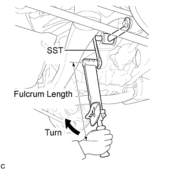 |
Using SST and a socket wrench (17 mm), fully tighten the bolt.
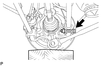 |
Fully tighten the bolt.
| 29. FULLY TIGHTEN REAR NO. 1 SUSPENSION ARM ASSEMBLY RH |
| 30. FULLY TIGHTEN REAR NO. 2 SUSPENSION ARM ASSEMBLY LH |
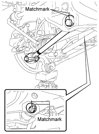 |
Align the matchmarks on the adjust cams and rear suspension member sub-assembly.
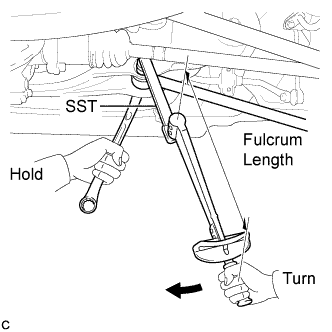 |
Using SST and a socket wrench (19 mm), fully tighten the nut.
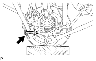 |
Fully tighten the bolt.
| 31. FULLY TIGHTEN REAR NO. 2 SUSPENSION ARM ASSEMBLY RH |
| 32. FULLY TIGHTEN REAR STRUT ROD ASSEMBLY LH |
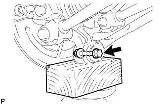 |
Fully tighten the bolt.
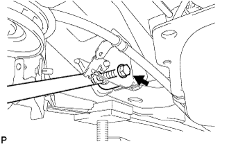 |
Fully tighten the bolt.
| 33. FULLY TIGHTEN REAR STRUT ROD ASSEMBLY RH |
| 34. INSTALL NO. 3 PARKING BRAKE CABLE ASSEMBLY |
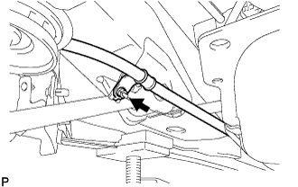 |
Install the No. 3 parking brake cable assembly with the nut.
| 35. INSTALL NO. 2 PARKING BRAKE CABLE ASSEMBLY |
| 36. INSTALL CENTER EXHAUST PIPE ASSEMBLY |
Inspect the compression spring.
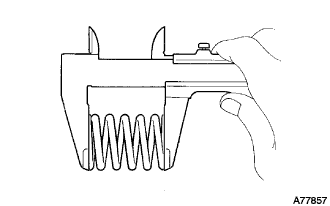 |
Using a vernier caliper, measure the free length of the compression spring.
| Minimum | 41.5 mm (1.634 in.) |
Fully insert a new gasket to the front No. 3 exhaust pipe sub-assembly.
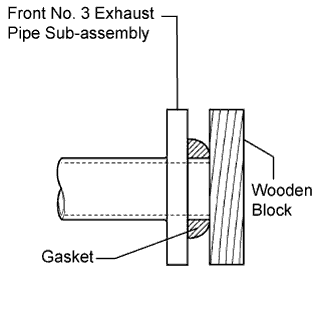 |
Using a plastic hammer and wooden block, tap in the new gasket until its surface is flush with the front No. 3 exhaust pipe sub-assembly.
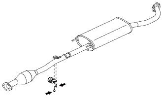 |
Install the damper with the 2 bolts.
Connect the center exhaust pipe assembly to the 3 exhaust pipe supports.
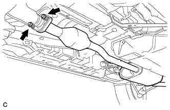 |
Tighten the 2 bolts and 2 compression springs.
| 37. INSTALL TAIL EXHAUST PIPE ASSEMBLY |
Inspect the compression spring.
|
Using a vernier caliper, measure the free length of the compression spring.
| Minimum | 40.5 mm (1.594 in.) |
Fully insert a new gasket to the center exhaust pipe assembly.
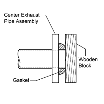 |
Using a plastic hammer and wooden block, tap in the new gasket until its surface is flush with the center exhaust pipe assembly
Connect the tail exhaust pipe assembly to the exhaust pipe support.
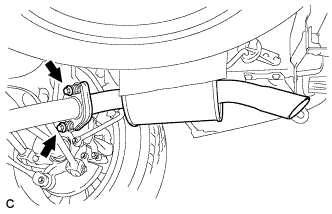 |
Tighten the 2 bolts and 2 compression springs.
| 38. CONNECT CABLE TO NEGATIVE BATTERY TERMINAL |
| 39. CHECK HIGH VOLTAGE CABLE CONNECTION |
|
Make sure that the No. 3 frame wire is securely installed with the nuts.
| 40. INSTALL SERVICE PLUG GRIP |
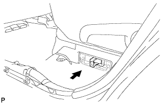 |
Wear insulated gloves, then insert the service plug.
Push down on the grip to lock.
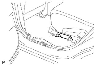 |
Close the reclining hinge cover.
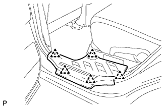 |
Close the rear door scuff plate LH.
| 41. INSPECT FOR EXHAUST GAS LEAK |
| 42. CHECK FOR SPEED SENSOR SIGNAL |
| 43. INSTALL REAR WHEELS |
| 44. INSPECT REAR WHEEL ALIGNMENT |