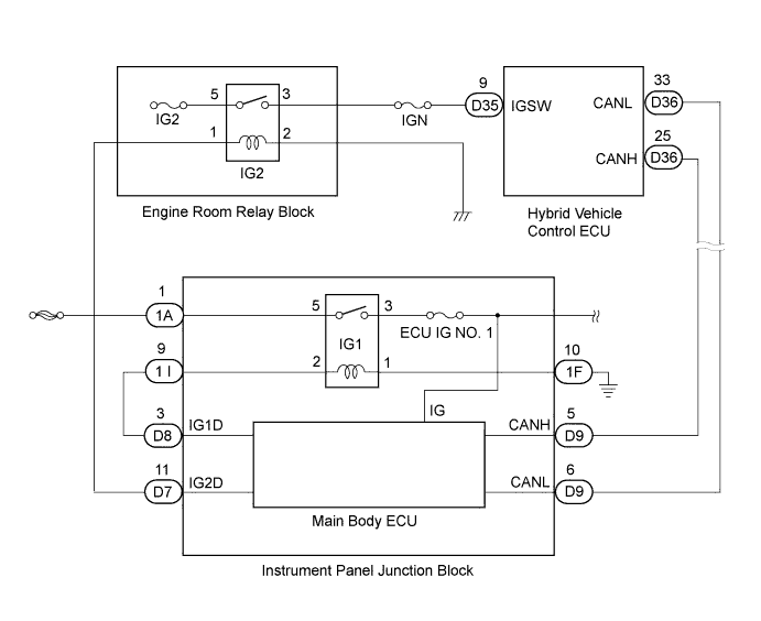
DTC P2532-772 Ignition Switch Run Position Circuit High |
| DTC No. | INF Code | DTC Detection Condition | Trouble Area |
| P2532 | 772 | When IG1 information from the ECUs that are connected to terminal IG1 of the power source control ECU is interrupted, the power source voltage is still applied to terminal IGSW. |
|
| 1.CLEAR DTC |
Connect the Techstream to the DLC3.
Turn the power switch on (IG).
Select the following menu items: Powertrain / Hybrid Control / Trouble Codes.
Read and record the DTCs and freeze frame data.
Select the following menu items: Powertrain / Hybrid Control / Trouble Codes.
Clear DTCs and freeze frame data.
| NEXT | |
 |
| 2.CHECK DTC OUTPUT (HV) |
Leave the vehicle for 15 seconds or more with the power switch on (IG) after clearing DTCs.
Select the following menu items: Powertrain / Hybrid Control / Trouble Codes.
Check if DTCs are output.
| Result | Proceed to |
| U0140-146 is not output but P2532-772 is output. | A |
| U0140-146 and P2532-772 are output. | B |
| Only DTCs other than U0140-146 and P2532-772 are output. | C |
| No DTC is output. | D |
|
| ||||
|
| ||||
|
| ||||
| A | |
|
| 3.CHECK FUSE (ECU IG NO. 1) |
Remove the ECU IG NO. 1 fuse from the instrument panel junction block.
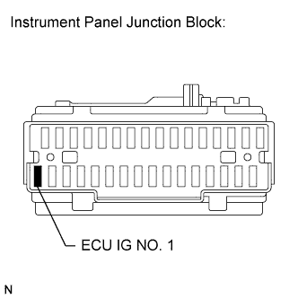 |
Measure the resistance according to the value(s) in the table below.
| Tester Connection | Switch Condition | Specified Condition |
| ECU IG NO. 1 fuse | Power switch off | Below 1 Ω |
|
| ||||
| OK | |
|
| 4.CHECK POWER SOURCE CIRCUIT (INSTRUMENT PANEL JUNCTION BLOCK) |
Turn the power switch off.
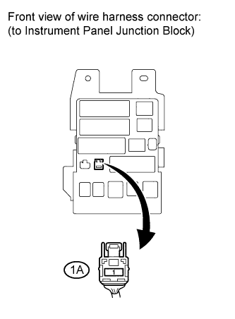 |
Disconnect connector 1A from the instrument panel junction block.
Measure the voltage according to the value(s) in the table below.
| Tester Connection | Switch Condition | Specified Condition |
| 1A-1 - Body ground | Power switch off | 11 to 14 V |
|
| ||||
| OK | |
|
| 5.CHECK WIRE HARNESS AND CONNECTOR |
Turn the power switch off.
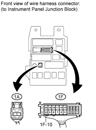 |
Disconnect the 1F connector from the instrument panel junction block.
Measure the resistance according to the value(s) in the table below.
| Tester Connection | Switch Condition | Specified Condition |
| 1F-10 - Body ground | Power switch off | Below 1 Ω |
|
| ||||
| OK | ||
 | ||
| ||
| 6.CHECK DTC OUTPUT (HV) |
Turn the power switch off.
Leave the vehicle for 1.5 seconds or more.
Turn the power switch on (IG).
Select the following menu items: Powertrain / Hybrid Control / Trouble Codes
Check if DTCs are output.
| Result | Proceed to |
| P2532-772 is output. | A |
| P2532-772 is not output. | B |
|
| ||||
| A | |
|
| 7.CHECK HYBRID VEHICLE CONTROL ECU |
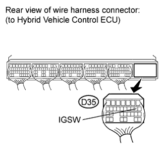 |
Turn the power switch off.
Disconnect connector D35 from the hybrid vehicle control ECU.
Measure the voltage according to the value(s) in the table below.
| Tester Connection | Switch Condition | Specified Condition |
| D35-9 (IGSW) - Body ground | Power switch off | Below 1 V |
|
| ||||
| OK | ||
| ||
| ||
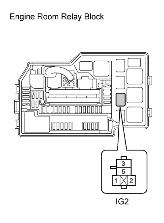
| 8.CHECK RELAY (IG2 RELAY) |
Turn the power switch off.
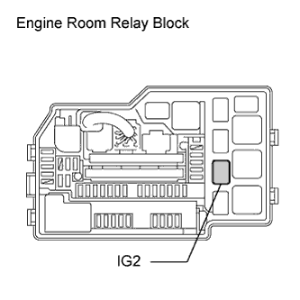 |
Remove the IG2 relay from the engine room relay block.
|
Measure the voltage according to the value(s) in the table below.
| Tester Connection | Switch Condition | Specified Condition |
| D35-9 (IGSW) - Body ground | Power switch off | Below 1 V |
|
| ||||
| OK | |
|
| 9.CHECK RELAY (IG2 RELAY) |
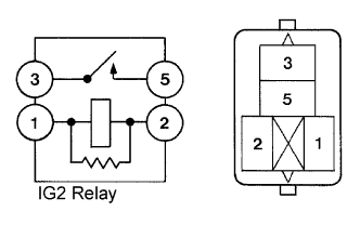 |
Measure the resistance according to the value(s) in the table below.
| Tester Connection | Condition | Specified Condition |
| 1 - 2 | Always | 130 to 235 Ω |
| 3 - 5 | Auxiliary battery voltage is not applied between terminals 1 and 2. | 10 kΩ or higher |
| Auxiliary battery voltage is applied between terminals 1 and 2. | Below 1 Ω |
|
| ||||
| OK | |
|
| 10.CHECK HARNESS AND CONNECTOR (INSTRUMENT PANEL JUNCTION BLOCK - IG2 RELAY) |
Turn the power switch off.
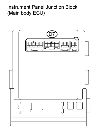 |
Disconnect connector D7 from the instrument panel junction block.
 |
Measure the voltage according to the value(s) in the table below.
| Tester Connection | Switch Condition | Specified Condition |
| IG2 relay terminal 1 - Body ground | Power switch off | Below 1 V |
|
| ||||
| OK | ||
| ||
| ||

