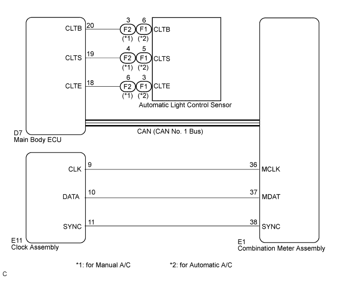
CLOCK SYSTEM > Illumination Circuit |
| 1.CONFIRM SYMPTOMS |
Confirm the symptom.
| Result | Proceed to |
| Only clock illumination has a malfunction. | A |
| Clock illumination, combination meter assembly illumination, and heater control panel illumination have a malfunction. | B |
|
| ||||
| A | |
 |
| 2.CHECK CAN COMMUNICATION SYSTEM |
Check if any DTC is output (Click here).
| Result | Proceed to |
| CAN communication DTC is not output. | A |
| CAN Communication DTC is output. | B |
|
| ||||
| A | |
|
| 3.PERFORM ACTIVE TEST USING TECHSTREAM |
Connect the Techstream to the DLC3.
Turn the power switch on (READY).
Turn the Techstream ON.
Turn the light control switch to the TAIL or HEAD position.
Enter the following menus: Body Electrical / Main Body / Active Test.
Check the clock illumination.
| Tester Display | Test Part | Control Range | Diagnostic Note |
| Dimmer signal | Dimmer signal | Dimmer signal is OFF/ON | Confirm that the vehicle is stopped, engine idling |
|
| ||||
| OK | ||
 | ||
| ||
| 4.CHECK HARNESS AND CONNECTOR (CLOCK ASSEMBLY - COMBINATION METER) |
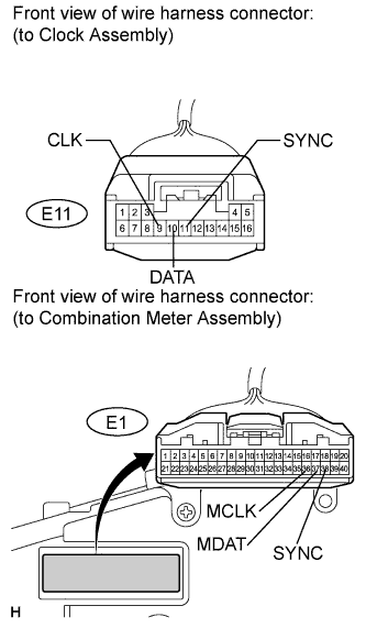 |
Disconnect the E1 and E11 connectors.
Measure the resistance according to the value(s) in the table below.
| Tester Connection | Condition | Specified Condition |
| E11-9 (CLK) - E1-36 (MCLK) | Always | Below 1 Ω |
| E11-10 (DATA) - E1-37 (MDAT) | Always | Below 1 Ω |
| E11-11 (SYNC) - E1-38 (SYNC) | Always | Below 1 Ω |
| E1-36 (MCLK) - Body ground | Always | 10 kΩ or higher |
| E1-37 (MDAT) - Body ground | Always | 10 kΩ or higher |
| E1-38 (SYNC) - Body ground | Always | 10 kΩ or higher |
|
| ||||
| OK | |
|
| 5.INSPECT COMBINATION METER ASSEMBLY |
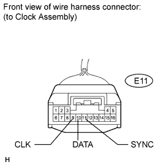 |
Reconnect the E1 connector.
Measure the voltage according to the value(s) in the table below.
| Tester Connection | Condition | Specified Condition |
| E11-9 (CLK) - Body ground | Power switch on (READY), headlight dimmer switch TAIL or HEAD | Pulse generation |
| E11-10 (DATA) - Body ground | Power switch on (READY), headlight dimmer switch TAIL or HEAD | Pulse generation |
| E11-11 (SYNC) - Body ground | Power switch on (READY), headlight dimmer switch TAIL or HEAD | Pulse generation |
| E11-9 (CLK) - Body ground | Power switch on (READY), headlight dimmer switch OFF | Below 1 V |
| E11-10 (DATA) - Body ground | Power switch on (READY), headlight dimmer switch OFF | Below 1 V |
| E11-11 (SYNC) - Body ground | Power switch on (READY), headlight dimmer switch OFF | Below 1 V |
|
| ||||
| OK | ||
| ||
| ||

