| B |  |
| GO TO DTC CHART (Click here) |
DTC P3004-131 Power Cable Malfunction |
DTC P3004-132 Power Cable Malfunction |
| DTC No. | INF Code | DTC Detection Condition | Trouble Area |
| P3004 | 131 | EV battery fuse is blown out, service plug grip is disconnected, SMR2 and SMR3 remain open, or the system main resistor is open. |
|
| 132 | Inverter voltage sensor malfunctions, or resistance of the system main resistor increases. |
| 1.CHECK DTC OUTPUT (HV) |
Connect the Techstream to the DLC3.
Turn the power switch on (IG).
Select the following menu items: Powertrain / Hybrid Control / Trouble Codes.
Check if DTCs are output.
| Result | Proceed to |
| P3004-131 or P3004-132 only is output. | A |
| DTCs other than P0A95, P0AE6-225, P0AE7-224, P0AE0-228 and P0ADF-229 are also output. | B |
|
| ||||
| A | |
 |
| 2.INSPECT HV RELAY ASSEMBLY (SMR1 AND SYSTEM MAIN RESISTOR) |
Turn the power switch off.
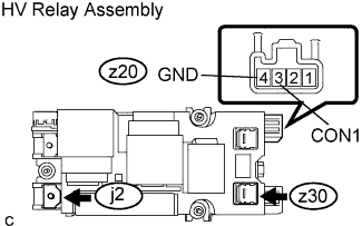 |
Remove the service plug grip (Click here).
Remove the HV relay assembly from the vehicle (Click here).
Measure the resistance according to the value(s) in the table below.
| Tester Connection | Condition | Specified Condition |
| z30-1 - j2-1 | Auxiliary battery voltage is applied between terminals z20-3 (CON1) and z20-4 (GND) | 28.5 to 31.5 Ω |
Measure the resistance according to the value(s) in the table below.
| Tester Connection | Condition | Specified Condition |
| z20-3 (CON1) - z20-4 (GND) | -31 to 176 °F (-35 to 80°C) | 70 to 165 Ω |
|
| ||||
| OK | |
|
| 3.INSPECT HV RELAY ASSEMBLY (SMR3) |
Check that the service plug grip is not installed.
Remove the HV relay assembly from the vehicle (Click here).
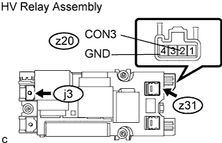 |
Measure the resistance according to the value(s) in the table below.
| Tester Connection | Condition | Specified Condition |
| j3-1 - z31-1 | Auxiliary battery voltage is applied between terminals z20-2 (CON3) and z20-4 (GND) | Below 1 Ω |
Measure the resistance according to the value(s) in the table below.
| Tester Connection | Condition | Specified Condition |
| z20-2 (CON3) - z20-4 (GND) | -31 to 176 °F (-35 to 80°C) | 20 to 60 Ω |
|
| ||||
| OK | |
|
| 4.INSPECT NO. 2 MAIN BATTERY CABLE (NEGATIVE SIDE) |
Measure the resistance according to the value(s) in the table below.
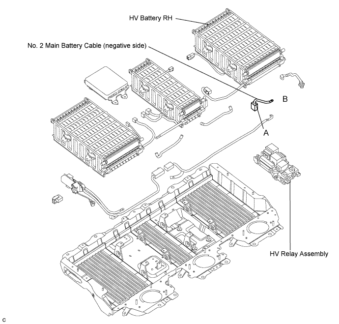
| Tester Connection | Switch Condition | Specified Condition |
| A - B | Power switch off | Below 1 Ω |
|
| ||||
| OK | |
|
| 5.INSPECT NO. 2 MAIN BATTERY CABLE (NEGATIVE SIDE), HV RELAY ASSEMBLY AND HV BATTERY |
Check that the nut that tightens the No. 2 main battery cable (negative side) is properly engaged with the connector on the HV battery terminal (RH side).
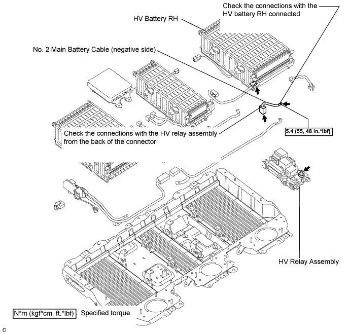
Check if the No. 2 main battery cable (negative side) is properly engaged with the connector on the HV relay assembly side.
|
| ||||
| OK | |
|
| 6.INSPECT HV BATTERY |
Measure the voltage according to the value(s) in the table below.
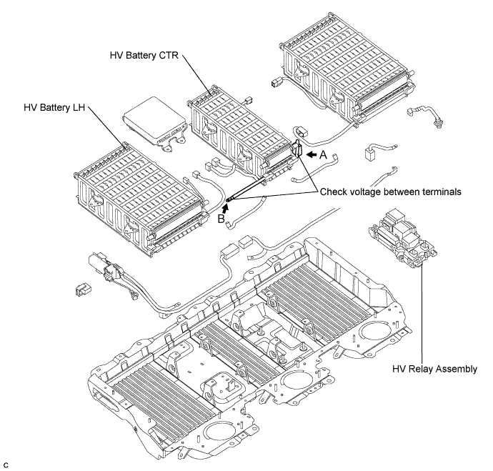
| Tester Connection | Switch Condition | Specified Condition |
| A (+) - B (-) | Power switch off | 40 to 80 V |
|
| ||||
| OK | |
|
| 7.INSPECT HV BATTERY AND HV RELAY ASSEMBLY |
Check if the cable on the HV relay assembly side connector in the HV battery CTR is properly engaged.
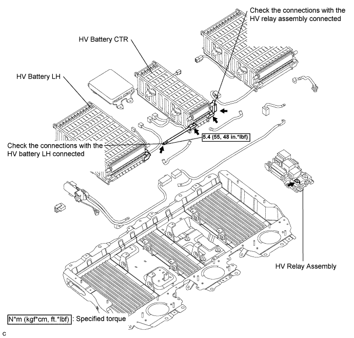
Check that the nut that tightens the HV battery CTR cable on the HV battery LH side is not loose.
|
| ||||
| OK | |
|
| 8.INSPECT NO. 3 FRAME WIRE |
Check that the service plug grip is not installed.
Remove the inverter cover (Click here).
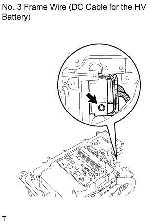 |
Disconnect the No. 3 frame wire (DC cable for the HV battery) from the inverter with converter assembly.
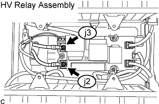 |
Disconnect the No. 3 frame wire (DC cable for the inverter with converter assembly) from the HV relay assembly.
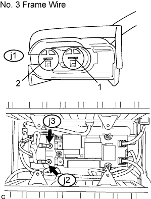 |
Measure the resistance according to the value(s) in the table below.
| Tester Connection | Switch Condition | Specified Condition |
| j1-2 - j2-1 | Power switch off | Below 1 Ω |
| j1-1 - j3-1 | Power switch off | Below 1 Ω |
|
| ||||
| OK | |
|
| 9.INSPECT INVERTER WITH CONVERTER ASSEMBLY (VH VOLTAGE) |
Turn the power switch on (IG).
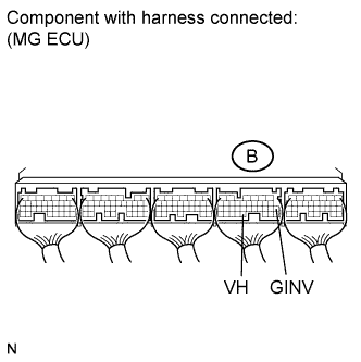 |
Measure the voltage according to the value(s) in the table below.
| Tester Connection | Switch Condition | Specified Condition |
| B-31 (VH) - B-17 (GINV) | Power switch on (IG) | 0.3 to 0.7 V |
|
| ||||
| OK | |
|
| 10.CHECK CONNECTOR CONNECTION CONDITION (HYBRID VEHICLE CONTROL ECU CONNECTOR) |
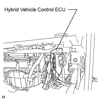 |
Check the connections of all hybrid vehicle control ECU connectors.
|
| ||||
| OK | |
|
| 11.CHECK HARNESS AND CONNECTOR (HYBRID VEHICLE CONTROL ECU - HV RELAY ASSEMBLY) |
Check that the service plug grip is not installed.
Disconnect the D36 connector from the hybrid vehicle control ECU.
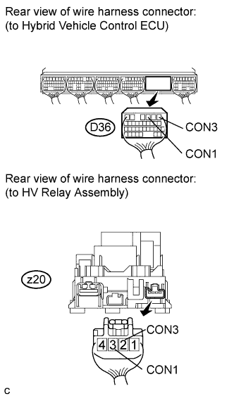 |
Measure the resistance according to the value(s) in the table below.
| Tester Connection | Switch Condition | Specified Condition |
| D36-3 (CON1) - z20-3 (CON1) | Power switch off | Below 1 Ω |
| D36-1 (CON3) - z20-2 (CON3) | Power switch off | Below 1 Ω |
|
| ||||
| OK | |
|
| 12.CHECK FOR INTERMITTENT PROBLEMS |
Check for intermittent problems (Click here).
| NEXT | |
|
| 13.CHECK DTC OUTPUT (HV) |
Select the following menu items: Powertrain / Hybrid Control / Trouble Codes.
Check if DTCs are output.
| Result | Proceed to |
| P3004-131 and P3004-132 are not output. | A |
| P3004-131 and P3004-132 are output again. | B |
|
| ||||
| A | ||
 | ||
| ||