EXTERIOR PANELS / TRIM BLACK OUT TAPE(for Rear Door) INSTALLATION
CAUTION / NOTICE / HINT
- HINT:
- ·
Use the same procedure for the RH side and LH side.
·The following procedure is for the LH side.
PROCEDURE

 1. REPAIR INSTRUCTION
75938
2.INSTALL UPPER INNER BLACK OUT TAPE
Refer to the illustration to position a new upper inner black out tape.
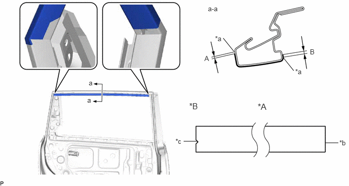
| *A | LH Side | *B | RH Side |
| *a | Edge of Curved Surface | *b | Straight |
| *c | Triangle | - | - |
- Standard Measurement:
Area Measurement Area Measurement A 1.0 mm (0.0394 in.) B 1.5 mm (0.0591 in.)
Remove the release paper and apply the upper inner black out tape.
75954A
3.INSTALL REAR INNER BLACK OUT TAPE
Refer to the illustration to position a new rear inner black out tape.
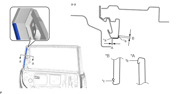
| *A | LH Side | *B | RH Side |
| *a | Edge of Curved Surface | *b | Straight |
| *c | Triangle | - | - |
- Standard Measurement:
Area Measurement Area Measurement A 1.0 mm (0.0394 in.) B 2.0 mm (0.0787 in.)
Remove the release paper and apply the rear inner black out tape.
75952A
4.INSTALL FRONT INNER BLACK OUT TAPE
Refer to the illustration to position a new front inner black out tape.
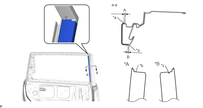
| *A | LH Side | *B | RH Side |
| *a | Edge of Curved Surface | *b | Straight |
| *c | Triangle | - | - |
- Standard Measurement:
Area Measurement Area Measurement A 1.5 mm (0.0591 in.) B 1.0 mm (0.0394 in.)
Remove the release paper and apply the front inner black out tape.
67673A
5.INSTALL REAR DOOR FRAME GARNISH (w/o Rear Door Sunshade)
67674A
6.INSTALL REAR DOOR FRAME GARNISH (w/ Rear Door Sunshade)
68104
7.INSTALL REAR DOOR GLASS SUB-ASSEMBLY
67408E
8.INSTALL REAR DOOR WINDOW DIVISION BAR SUB-ASSEMBLY
68152C
9.INSTALL REAR DOOR GLASS RUN
67872
10.CONNECT REAR DOOR WEATHERSTRIP
67858B
11.INSTALL REAR DOOR PANEL PROTECTOR
67842E
12.INSTALL REAR DOOR SERVICE HOLE COVER
67604
13.INSTALL REAR DOOR TRIM BOARD SUB-ASSEMBLY
67488C
14.INSTALL REAR DOOR REAR GUIDE SEAL
15.INSTALL REAR POWER WINDOW REGULATOR SWITCH ASSEMBLY WITH REAR DOOR UPPER ARMREST BASE PANEL
69284D
16.INSTALL REAR DOOR INSIDE HANDLE BEZEL PLUG
17.CONNECT CABLE TO NEGATIVE BATTERY TERMINAL
- NOTICE:
-
When disconnecting the cable, some systems need to be initialized after the cable is reconnected.
-
Click hereGeneral>INTRODUCTION>REPAIR INSTRUCTION>INITIALIZATION
18. INITIALIZE POWER WINDOW CONTROL SYSTEM (for Models with Jam Protection Function on 4 Windows)
19.INSPECT POWER WINDOW OPERATION
for Models with Jam Protection Function on 4 Windows:
for Models with Jam Protection Function on Front Door Windows: