BRAKE SYSTEM (OTHER) VACUUM PUMP REMOVAL
PROCEDURE

 1. PRECAUTION
- NOTICE:
-
After turning the ignition switch off, waiting time may be required before disconnecting the cable from the negative (-) battery terminal. Therefore, make sure to read the disconnecting the cable from the negative (-) battery terminal notices before proceeding with work.
-
Click hereGeneral>INTRODUCTION>REPAIR INSTRUCTION>PRECAUTION
2.DISCONNECT CABLE FROM NEGATIVE BATTERY TERMINAL
- NOTICE:
-
When disconnecting the cable, some systems need to be initialized after the cable is reconnected.
-
Click hereGeneral>INTRODUCTION>REPAIR INSTRUCTION>INITIALIZATION
22030
3.REMOVE THROTTLE BODY WITH MOTOR ASSEMBLY
4.REMOVE FRONT WHEEL LH
5.REMOVE WINDSHIELD WIPER MOTOR AND LINK ASSEMBLY
55701J
6.REMOVE OUTER COWL TOP PANEL SUB-ASSEMBLY
for LHD: Click hereSuspension>FRONT SUSPENSION>FRONT SHOCK ABSORBER>REMOVAL
for RHD: Click hereSuspension>FRONT SUSPENSION>FRONT SHOCK ABSORBER>REMOVAL
53299D
7.REMOVE RADIATOR SIDE DEFLECTOR SEAL LH
53298E
8.REMOVE RADIATOR SIDE SEAL RH
53295E
9.REMOVE COOL AIR INTAKE DUCT SEAL
11209
10.REMOVE V-BANK COVER SUB-ASSEMBLY
17750A
11.REMOVE INLET AIR CLEANER ASSEMBLY
17801
12.REMOVE AIR CLEANER FILTER ELEMENT SUB-ASSEMBLY
17701
13.REMOVE AIR CLEANER CASE SUB-ASSEMBLY
33820B
14.SEPARATE TRANSMISSION CONTROL CABLE ASSEMBLY
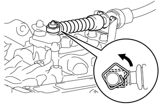
Remove the clip from the transmission control shaft lever as shown in the illustration.
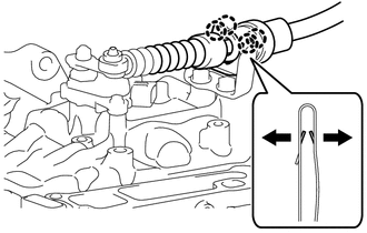
Using a screwdriver, disengage the 4 claws and disconnect the transmission control cable assembly with the clip from the No. 1 transmission control cable bracket.
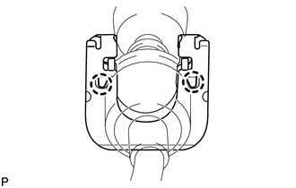
Using a screwdriver, disengage the 2 claws and disconnect the clip from the transmission control cable assembly.
17361M
15.DISCONNECT AIR TUBE
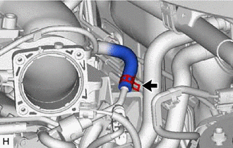
Slide the clip and disconnect the air tube from the vacuum pump assembly.
12261
16.DISCONNECT VENTILATION HOSE
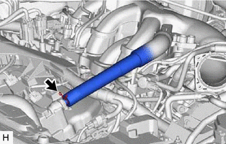
Slide the clip and disconnect the ventilation hose.
17.DISCONNECT HEATER WATER HOSE
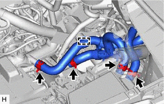
Disengage the clamp.
Slide the 4 clips and disconnect the 4 heater water hoses.
51442
18.REMOVE NO. 2 ENGINE UNDER COVER
82121
19.SEPARATE ENGINE WIRE
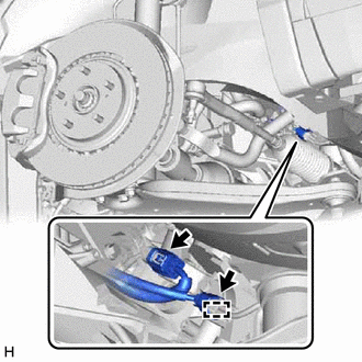
Disconnect the 2 connectors.
Disengage the clamp.
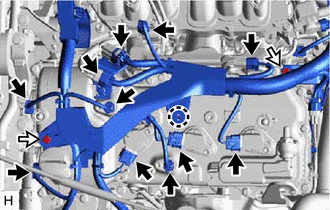

|
Connector |

|
Bolt |
Disconnect the 11 connectors.
Disengage the claw.
Remove the 2 bolts.
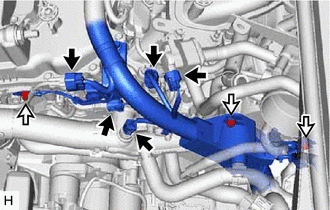
|
|
Connector |
|
|
Bolt |
Disconnect the 5 connectors.
Remove the 3 bolts.
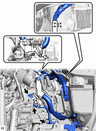
|
|
Connector |
|
|
Bolt |

|
Nut |
Disengage the clamp.
Disconnect the 3 connectors.
Remove the 2 bolts and nut to separate the engine wire.
29300
20.REMOVE VACUUM PUMP ASSEMBLY
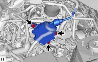
Remove the 3 bolts and vacuum pump assembly from the engine assembly.
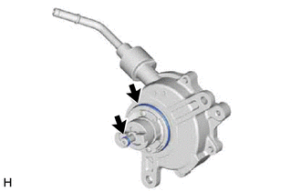
Remove the 2 O-rings from the vacuum pump assembly.