DRIVE SHAFT / PROPELLER SHAFT PROPELLER SHAFT ASSEMBLY REMOVAL
PROCEDURE

 51442
1.REMOVE NO. 2 ENGINE UNDER COVER
58166
2.REMOVE FRONT FLOOR COVER LH
58167A
3.REMOVE FRONT CENTER FLOOR COVER
4.REMOVE WIRING HARNESS CLAMP BRACKET
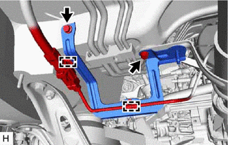
Disengage the 2 clamps.
Remove the 2 bolts and wiring harness clamp bracket.
51569F
5.REMOVE PROPELLER SHAFT GUARD (for Front Side)
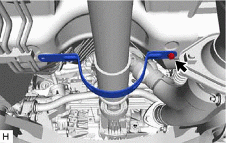
Remove the bolt and propeller shaft guard.
51569G
6.REMOVE PROPELLER SHAFT GUARD (for Rear Side)
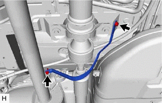
Remove the bolt, nut and propeller shaft guard.
37100
7.REMOVE PROPELLER WITH CENTER BEARING SHAFT ASSEMBLY
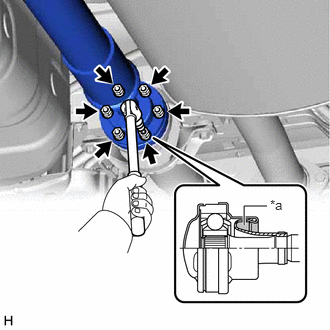
| *a | Piece of Cloth |
Using a 6 mm hexagon socket wrench, loosen the 6 cross groove joint set bolts 1/2 turn.
- NOTICE:
- ·
Put a piece of cloth or equivalent into the inside of the universal joint cover so that the boot does not touch the inside of the universal joint cover.
·Do not remove the cross groove joint set bolts.
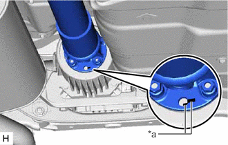
| *a | Matchmark |
Put matchmarks on the electro magnetic control coupling sub-assembly and propeller with center bearing shaft assembly.
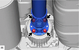
Remove the 4 nuts and 4 washers.
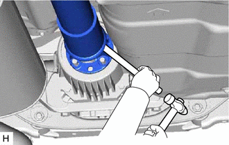
Using a brass bar and a hammer, separate the propeller with center bearing shaft assembly.
- NOTICE:
-
Use wire or an equivalent tool to keep the propeller with center bearing shaft assembly.
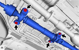
Remove the 4 bolts and 4 No. 2 center support bearing washers.
- NOTICE:
-
When removing the bolts and No. 2 center support bearing washers, do not apply excessive force to the universal joint.
Pull out the propeller with center bearing shaft assembly from the transfer assembly.
- NOTICE:
- ·
When removing the propeller with center bearing shaft assembly, do not apply excessive force to the universal joint.
·During and after the removal of the propeller with center bearing shaft assembly, keep the universal joint angle straight (within 15 degrees).
·Be careful not to damage the transfer case rear oil seal.
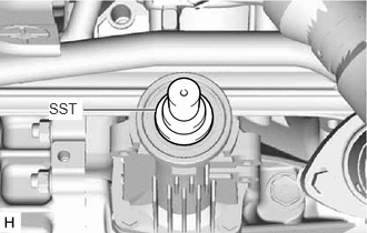
Insert SST in the transfer assembly to prevent oil leakage.
- SST
- 09325-20010
- NOTICE:
-
Be careful not to damage the transfer extension housing type T oil seal.