AXLE AND DIFFERENTIAL REAR AXLE CARRIER(for AWD) REMOVAL
CAUTION / NOTICE / HINT
- HINT:
- ·
Use the same procedure for the RH side and LH side.
·The procedure listed below is for the LH side.
PROCEDURE

 1.REMOVE REAR WHEEL
2.DRAIN BRAKE FLUID
- NOTICE:
-
If brake fluid leaks onto any painted surface, immediately wash it off.
42312B
3.REMOVE REAR AXLE SHAFT NUT
4.REMOVE REAR DISC BRAKE CALIPER ASSEMBLY
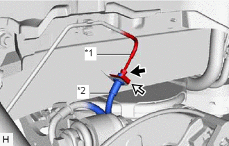
| *1 | Rear Brake Tube |
| *2 | Rear Flexible Hose |

|
Clip |
Using a union nut wrench, separate the rear flexible hose from the rear brake tube while holding the rear flexible hose with a wrench.
- NOTICE:
- ·
Do not kink or damage the brake line.
·Do not allow any foreign matter such as dirt or dust to enter the brake line from the connecting parts.
Remove the clip and separate the rear flexible hose.
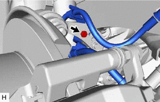
Remove the bolt and separate the rear flexible hose from the rear upper control arm assembly.
Remove the 2 bolts and rear disc brake caliper assembly with rear flexible hose.
42491
5.REMOVE PARKING BRAKE SHOE ADJUSTING HOLE PLUG
Click hereBrake>BRAKE (REAR)>REAR BRAKE>REMOVAL
42431
6.REMOVE REAR DISC
Click hereBrake>BRAKE (REAR)>REAR BRAKE>REMOVAL
89546
7.SEPARATE REAR SPEED SENSOR
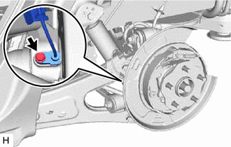
Remove the bolt and separate the rear speed sensor from the rear axle carrier sub-assembly.
- NOTICE:
- ·
Prevent foreign matter from contacting the sensor tip.
·Clean the speed sensor installation hole and the contact surfaces every time the speed sensor is removed.
·Be careful not to damage the rear speed sensor.
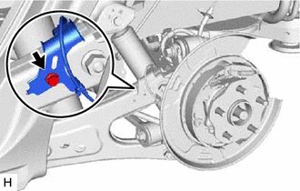
Remove the bolt and separate the rear speed sensor from the rear trailing arm assembly.
42440
8.REMOVE REAR AXLE HUB AND BEARING ASSEMBLY
9.LOOSEN PARKING BRAKE ASSEMBLY
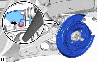
Loosen the nut to separate the parking brake assembly after removing the rear trailing arm assembly.
48780E
10.REMOVE REAR TRAILING ARM ASSEMBLY
11.SEPARATE PARKING BRAKE ASSEMBLY
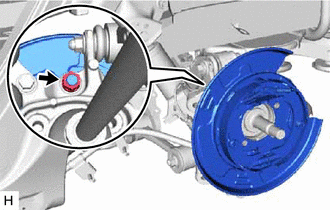
Remove the nut and separate the parking brake assembly from the rear axle carrier sub-assembly.
- NOTICE:
-
Use wire or an equivalent tool to keep the parking brake assembly from hanging by the parking brake cable.
42305
12.REMOVE REAR AXLE CARRIER SUB-ASSEMBLY
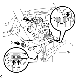
| *a | Wooden Block |
| *b | Jack |
Support the rear No. 2 suspension arm assembly using a jack and wooden block.
- CAUTION:
-
Do not jack up the rear No. 2 suspension arm assembly too high as the vehicle may fall.
- NOTICE:
- ·
When jacking up the rear No. 2 suspension arm assembly, be sure to jack it up slowly.
·Keep supporting the rear No. 2 suspension arm assembly until the installation of the rear axle carrier sub-assembly has been completed.
Remove the 2 bolts (A), and separate the rear axle carrier sub-assembly from the rear lower shock absorber bracket sub-assembly.
Remove the bolt (B) and nut, and separate the rear upper control arm assembly from the rear axle carrier sub-assembly.
- NOTICE:
-
Because the nut has its own stopper, do not turn the nut. Loosen the bolt with the nut secured.
Remove the bolt (C) and nut, and separate the rear axle carrier sub-assembly from the rear No. 2 suspension arm assembly.
- NOTICE:
-
Because the nut has its own stopper, do not turn the nut. Loosen the bolt with the nut secured.
Remove the nut (D), spacer and rear axle carrier sub-assembly from the rear No. 1 suspension arm assembly.
- NOTICE:
-
Use wire or an equivalent tool to keep the rear drive shaft assembly from hanging down.
48759
13.REMOVE LOWER CONTROL ARM PIN
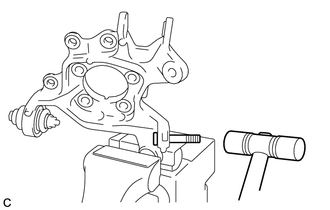
Secure the rear axle carrier sub-assembly in a vise using aluminum plates.
- NOTICE:
-
Do not overtighten the vise.
Using a hammer, remove the lower control arm pin from the rear axle carrier sub-assembly.