REAR SUSPENSION REAR LOWER ARM INSTALLATION
CAUTION / NOTICE / HINT
- HINT:
- ·
Use the same procedure for the RH side and LH side.
·The procedure listed below is for the LH side.
PROCEDURE

 48720A
1.TEMPORARILY INSTALL REAR NO. 1 SUSPENSION ARM ASSEMBLY
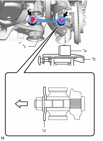
| *a | Wooden Block |
| *b | Jack |
| *c | Opening |
| *d | Spacer |

|
Front of the Vehicle |
Temporarily install the rear No. 1 suspension arm assembly to the rear axle carrier sub-assembly with the spacer and nut (A).
- NOTICE:
- ·
Install the rear No. 1 suspension arm assembly with its opening facing downward.
·Fully tighten the nut (A) after stabilizing the suspension.
·Be sure to install the rear No. 1 suspension arm assembly with the spacer facing in the correct direction as shown in the illustration.
Temporarily install the rear No. 1 suspension arm assembly to the rear suspension member sub-assembly with the bolt (B) and nut.
- NOTICE:
- ·
Insert the bolt with the threaded end facing the rear of the vehicle.
·Because the nut has its own stopper, do not turn the nut. Tighten the bolt with the nut secured.
·Fully tighten the bolt (B) after stabilizing the suspension.
Slowly lower the rear axle assembly.
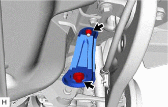
Install the rear lower suspension member stopper with the bolt and nut.
- Torque:
- Bolt : 158 N*m (1611 kgf*cm, 117 ft.*lbf)
- Nut : 32 N*m (326 kgf*cm, 24 ft.*lbf)
Slowly lower the jack.
48740F
2.TEMPORARILY INSTALL REAR NO. 2 SUSPENSION ARM ASSEMBLY
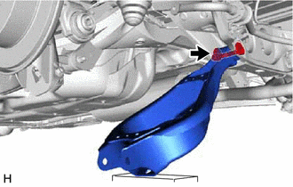
Temporarily install the rear No. 2 suspension arm assembly to the rear suspension member sub-assembly with the No. 2 adjust cam, toe adjust cam sub-assembly and the nut.
- NOTICE:
- ·
Insert the toe adjust cam sub-assembly with the threaded end facing the front of the vehicle.
·When tightening the nut, keep the toe adjust cam sub-assembly from rotating.
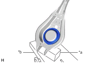
| *a | Wooden Block |
| *b | Jack |
Support the rear No. 2 suspension arm assembly using a jack and wooden block.
Install the rear lower coil spring insulator to the rear No. 2 suspension arm assembly.
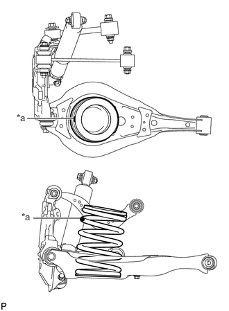
| *a | Identification Mark |
Set the rear coil spring to the rear No. 2 suspension arm assembly.
- NOTICE:
-
Set the rear coil spring so that the identification mark is positioned as shown in the illustration.
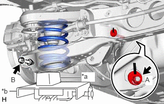
| *a | Wooden Block |
| *b | Jack |
Using a jack and wooden block, slowly jack up the rear No. 2 suspension arm assembly and then temporarily install the rear No. 2 suspension arm assembly to the rear axle assembly with the bolt (B) and nut.
- Torque:
- 100 N*m (1020 kgf*cm, 74 ft.*lbf)
- CAUTION:
-
Do not jack up the rear No. 2 suspension arm assembly too high as the vehicle may fall.
- NOTICE:
- ·
Because the nut has its own stopper, do not turn the nut. Tighten the bolt with the nut secured.
·When jacking up the rear No. 2 suspension arm assembly, be sure to jack it up slowly.
·Insert the bolt with the threaded end facing the front of the vehicle.
·Fully tighten the nut (A) after stabilizing the suspension.
48802
3.INSTALL REAR STABILIZER LINK SUB-ASSEMBLY
4.STABILIZE SUSPENSION
48720A
5.INSTALL REAR NO. 1 SUSPENSION ARM ASSEMBLY
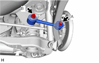
Using a ball joint lock nut wrench, install the rear No. 1 suspension arm assembly with the bolt (B).
- Torque:
- 150 N*m (1530 kgf*cm, 111 ft.*lbf)
- NOTICE:
- ·
Because the nut has its own stopper, do not turn the nut. Tighten the bolt (B) with the nut secured.
·Use the formula to calculate special torque values for situations where the union nut wrench is combined with a torque wrench.
Click hereGeneral>INTRODUCTION>REPAIR INSTRUCTION>PRECAUTION
Install the rear No. 1 suspension arm assembly with the nut (A).
- Torque:
- 145 N*m (1479 kgf*cm, 107 ft.*lbf)
6.INSTALL REAR WHEEL
- Torque:
- 103 N*m (1050 kgf*cm, 76 ft.*lbf)
48740F
7.INSTALL REAR NO. 2 SUSPENSION ARM ASSEMBLY
Lower the vehicle to the ground.
Bounce the vehicle up and down at the corners to stabilize the rear suspension.
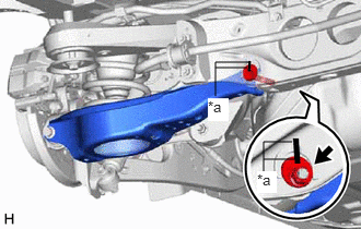
| *a | Matchmark |
Install the rear No. 2 suspension arm assembly with the nut.
- Torque:
- 100 N*m (1020 kgf*cm, 74 ft.*lbf)
- NOTICE:
- ·
Align the matchmarks on the toe adjust cam sub-assembly, No. 2 adjust cam and rear suspension member sub-assembly.
·Hold the toe adjust cam sub-assembly while rotating the nut.
·Tighten the nut while the vehicle is unloaded.
8.INSPECT AND ADJUST REAR WHEEL ALIGNMENT