DOOR / HATCH POWER BACK DOOR SYSTEM Back Door Closer does not Operate
DESCRIPTION
If the back door closer does not operate, one of the following may be the cause: 1) improper fit of the back door or a foreign object stuck in the back door, 2) a malfunction in the multiplex network door ECU power source circuit, 3) a malfunction in the back door lock with courtesy light switch assembly circuit, 4) initialization of the multiplex network door ECU has not been performed or 5) a multiplex network door ECU malfunction.
WIRING DIAGRAM
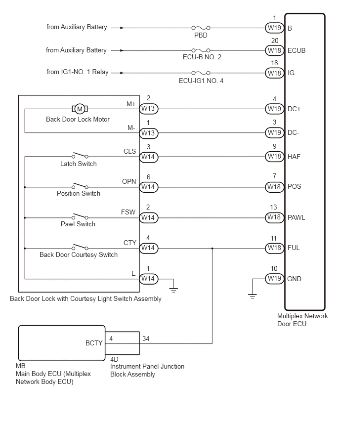
CAUTION / NOTICE / HINT
- NOTICE:
- ·
Inspect the fuses for circuits related to this system before performing the following procedure.
·If the multiplex network door ECU has been removed and installed or replaced, or if any of the connectors have been disconnected, initialize the power back door system.
Click hereVehicle Exterior>DOOR / HATCH>POWER BACK DOOR SYSTEM>INITIALIZATION
PROCEDURE
Check for DTCs.
- Body Electrical > Back Door > Trouble Codes
- 50001 159
- Result:
Result Proceed to DTC is not output A DTC B2250 is output B DTC B2251 is output C
A
B
C
Check if the back door can be fully closed by hand.
- Result:
Result Proceed to The back door can be closed normally A The back door cannot be closed normally B
A
B
Initialize the power back door system.
Click hereVehicle Exterior>DOOR / HATCH>POWER BACK DOOR SYSTEM>INITIALIZATION
- Result:
Proceed to NEXT
NEXT
When the back door is partially closed, check that the motor operates to fully close the back door.
- Result:
Result Proceed to The back door closer operates normally A The back door closer does not operate normally B
A
B
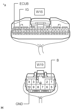
| *a | Rear view of wire harness connector
(to Multiplex Network Door ECU) |
Measure the resistance according to the value(s) in the table below.
- Standard Resistance:
Tester Connection Condition Specified Condition W19-10 (GND) - Body ground Always Below 1 Ω
Measure the voltage according to the value(s) in the table below.
- Standard Voltage:
Tester Connection Condition Specified Condition W18-20 (ECUB) - Body ground Ignition switch off*1
Always*211 to 14 V W19-1 (B) - Body ground Ignition switch off*1
Always*211 to 14 V W18-18 (IG) - Body ground Ignition switch ON 11 to 14 V Ignition switch off Below 1 V
*1: for HV Model
*2: for Gasoline Model
- Result:
Proceed to OK NG
OK
NG
OK
NG
Disconnect the W18 and W19 multiplex network door ECU connectors.
Measure the resistance according to the value(s) in the table below.
- Standard Resistance:
Tester Connection Condition Specified Condition W13-2 (M+) - W19-4 (DC+) Always Below 1 Ω W13-1 (M-) - W19-3 (DC-) Always Below 1 Ω W14-4 (CTY) - W18-11 (FUL) Always Below 1 Ω W14-2 (FSW) - W18-13 (PAWL) Always Below 1 Ω W14-3 (CLS) - W18-9 (HAF) Always Below 1 Ω W14-6 (OPN) - W18-7 (POS) Always Below 1 Ω W14-1 (E) - Body ground Always Below 1 Ω W13-2 (M+) or W19-4 (DC+) - Body ground Always 10 kΩ or higher W13-1 (M-) or W19-3 (DC-) - Body ground Always 10 kΩ or higher W14-4 (CTY) or W18-11 (FUL) - Body ground Always 10 kΩ or higher W14-2 (FSW) or W18-13 (PAWL) - Body ground Always 10 kΩ or higher W14-3 (CLS) or W18-9 (HAF) - Body ground Always 10 kΩ or higher W14-6 (OPN) or W18-7 (POS) - Body ground Always 10 kΩ or higher
- Result:
Proceed to OK NG
OK
NG