GF2A TRANSFER / 4WD / AWD DYNAMIC TORQUE CONTROL AWD SYSTEM AWD Control Switch Circuit
WIRING DIAGRAM
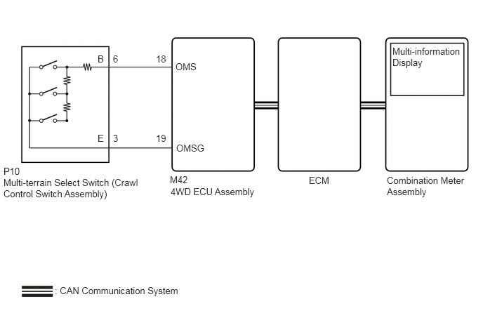
CAUTION / NOTICE / HINT
- NOTICE:
-
When the 4WD ECU assembly is replaced, before removing the 4WD ECU assembly, it is necessary to perform ECU Data Save to save the original 4WD ECU assembly information.
-
Click hereDrivetrain>GF2A (TRANSFER / 4WD / AWD)>DYNAMIC TORQUE CONTROL AWD SYSTEM>CALIBRATION
PROCEDURE
Simultaneously display the "Off-road Mode Selection Signal" four wheel drive Data List item and the "Off-road Guidance Status" engine Data List item.
According to the display on the GTS, read the Data List.
- Chassis > Four Wheel Drive > Data List
-
Tester Display Measurement Item Range Normal Condition Diagnostic Note Off-road Mode Selection Signal Off-road mode selection signal Normal / Grass & Snow / Mud & Sand / Loose Rock / Mogul / Rock & Dirt / Rock / E-Lock - -
- Powertrain > Engine > Data List
-
Tester Display Measurement Item Range Normal Condition Diagnostic Note Off-road Guidance Status Off road mode status Normal / Grass & Snow / Mud & Sand / Loose Rock / Mogul or Rock & Dirt - -
- Chassis > Four Wheel Drive > Data List
-
Tester Display Off-road Mode Selection Signal - 50003 448 54
- Powertrain > Engine > Data List
-
Tester Display Off-road Guidance Status - 50003 372 1098
Operate the multi-terrain select switch (crawl control switch assembly) and check that the Data List display and multi-information display message change according to switch operation.
- OK:
Multi-terrain Select Switch (Crawl Control Switch Assembly) Operation Data List Display Multi-information Display Message NORMAL Normal - MUD&SAND Mud & Sand MUD&SAND ROCK&DIRT Rock & Dirt ROCK&DIRT
- Result:
Result Proceed to When the switch is operated, the Data List display (Off-road Mode Selection Signal and Off-road Guidance Status) and message do not change A When the switch is operated, the Data List display (Off-road Mode Selection Signal) changes, but the Data List display (Off-road Guidance Status) and message do not change B When the switch is operated, the Data List display (Off-road Mode Selection Signal and Off-road Guidance Status) changes, but the message does not change C When the switch is operated, the Data List display and message change normally D
A
B
C
Click hereVehicle Interior>METER / GAUGE / DISPLAY>METER / GAUGE SYSTEM>HOW TO PROCEED WITH TROUBLESHOOTING
D
Click hereGeneral>INTRODUCTION>HOW TO TROUBLESHOOT ECU CONTROLLED SYSTEMS>HOW TO PROCEED WITH TROUBLESHOOTING
Click hereDrivetrain>GF2A (TRANSFER / 4WD / AWD)>MULTI-TERRAIN SELECT SWITCH>INSPECTION
- Result:
Proceed to OK NG
OK
NG
Disconnect the M42 4WD ECU assembly connector.
Disconnect the P10 multi-terrain select switch (crawl control switch assembly) connector.
Measure the resistance according to the value(s) in the table below.
- Standard Resistance:
Tester Connection Condition Specified Condition M42-18 (OMS) - P10-6 (B) Always Below 1 Ω M42-19 (OMSG) - P10-3 (E) Always Below 1 Ω M42-18 (OMS) or P10-6 (B) - Body ground Always 10 kΩ or higher M42-19 (OMSG) or P10-3 (E) - Body ground Always 10 kΩ or higher M42-18 (OMS) or P10-6 (B) - M42-19 (OMSG) or P10-3 (E) Always 10 kΩ or higher
- Result:
Proceed to OK NG
OK
NG