Home › Vehicle Interior › METER / GAUGE / DISPLAY › METER / GAUGE SYSTEM › from 2020.11
RM37A0E _58 Vehicle Interior _086889 METER / GAUGE / DISPLAY _0416706 METER / GAUGE SYSTEM J

METER / GAUGE / DISPLAY  METER / GAUGE SYSTEM  Steering Pad Switch Circuit  


DESCRIPTION

The combination meter assembly and steering pad switch assembly are connected via direct line. The multi-information display in the combination meter assembly is operated using the switches of the steering pad switch assembly.

WIRING DIAGRAM
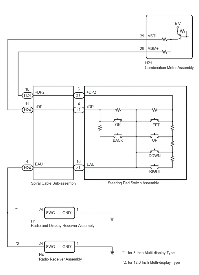
E430484E03
5.229,2.177 5.542,2.375 0.313,0.198 10 false H21 5.219,2.344 7.083,2.802 1.865,0.458 10 false Combination Meter Assembly 1.115,6.5 4.938,6.698 3.823,0.198 10 false Spiral Cable Sub-assembly 3.885,6.49 6.073,6.802 2.188,0.313 10 false Steering Pad Switch Assembly 1.115,7.865 1.573,8.063 0.458,0.198 10 false H1 1.115,8.021 6.469,8.219 5.354,0.198 10 false Radio and Display Receiver Assembly 1.406,9.229 4.927,9.427 3.521,0.198 10 false Radio Receiver Assembly 0.552,7.448 0.865,7.646 0.313,0.198 10 false *1 0.563,8.667 0.875,8.865 0.313,0.198 10 false *2 4.406,9 6.375,9.333 1.969,0.333 10 false *1: for 8 Inch Multi-display Type 4.406,9.344 7.094,9.615 2.688,0.271 10 false *2: for 12.3 Inch Multi-display Type 5.313,1.656 5.927,1.854 0.615,0.198 10 false MSM+ 5.313,1.208 5.927,1.406 0.615,0.198 10 false MSTI 6.302,0.76 6.917,0.958 0.615,0.198 10 false 5 V 5.042,1.208 5.656,1.406 0.615,0.198 10 false 29 5.042,1.656 5.656,1.854 0.615,0.198 10 false 28 1.26,3.229 1.875,3.427 0.615,0.198 10 false +DP2 1.26,3.75 1.875,3.948 0.615,0.198 10 false +DP 0.865,3.344 1.479,3.542 0.615,0.198 10 false H24 2.792,3.115 3.406,3.313 0.615,0.198 10 false 5 2.802,3.646 3.417,3.844 0.615,0.198 10 false 4 0.938,5.719 1.552,5.917 0.615,0.198 10 false 4 2.75,5.938 3.365,6.135 0.615,0.198 10 false z1 2.75,5.719 3.365,5.917 0.615,0.198 10 false 10 0.906,3.125 1.521,3.323 0.615,0.198 10 false 10 0.906,3.646 1.521,3.844 0.615,0.198 10 false 11 4.146,4.396 4.76,4.594 0.615,0.198 10 false OK 5.417,4.406 6.031,4.604 0.615,0.198 10 false LEFT 4.063,4.958 4.677,5.156 0.615,0.198 10 false BACK 5.354,5.51 5.969,5.708 0.615,0.198 10 false DOWN 5.479,4.958 6.094,5.156 0.615,0.198 10 false UP 5.375,6.073 5.99,6.271 0.615,0.198 10 false RIGHT 1.396,7.448 2.01,7.646 0.615,0.198 10 false 24 2.75,7.448 3.365,7.646 0.615,0.198 10 false 1 1.656,7.563 2.271,7.76 0.615,0.198 10 false SWG 2.25,7.563 2.865,7.76 0.615,0.198 10 false GND1 1.406,9.073 2.021,9.271 0.615,0.198 10 false H4 1.656,8.781 2.271,8.979 0.615,0.198 10 false SWG 2.25,8.781 2.865,8.979 0.615,0.198 10 false GND1 1.26,5.813 1.719,6.01 0.458,0.198 10 false EAU 0.865,3.865 1.479,4.063 0.615,0.198 10 false H24 0.865,5.948 1.479,6.146 0.615,0.198 10 false H24 2.76,3.854 3.375,4.052 0.615,0.198 10 false z1 2.75,3.333 3.365,3.531 0.615,0.198 10 false z1 1.396,8.667 2.01,8.865 0.615,0.198 10 false 24 2.76,8.667 3.375,8.865 0.615,0.198 10 false 1 3.115,3.229 3.729,3.427 0.615,0.198 10 false +DP2 3.104,3.75 3.719,3.948 0.615,0.198 10 false +DP 3.125,5.823 3.583,6.021 0.458,0.198 10 false EAU

CAUTION / NOTICE / HINT

NOTICE:

When replacing the combination meter assembly, always replace it with a new one. If a combination meter assembly which was installed to another vehicle is used, the information stored in it will not match the information from the vehicle and a DTC may be stored.


PROCEDURE

1.INSPECT STEERING PAD SWITCH ASSEMBLY
a.

Remove the steering pad switch assembly.

Click hereSteering>STEERING COLUMN>STEERING PAD SWITCH>REMOVAL


b.

Inspect the steering pad switch assembly.

Click hereSteering>STEERING COLUMN>STEERING PAD SWITCH>INSPECTION


Result:
Proceed to
OK
NG


OK

2.INSPECT SPIRAL CABLE SUB-ASSEMBLY

NG

REPLACE STEERING PAD SWITCH ASSEMBLY

2.INSPECT SPIRAL CABLE SUB-ASSEMBLY
a.

Remove the spiral cable sub-assembly.

Click hereVehicle Interior>SUPPLEMENTAL RESTRAINT SYSTEMS>SPIRAL CABLE>REMOVAL


b.

Inspect the spiral cable sub-assembly.

Click hereVehicle Interior>SUPPLEMENTAL RESTRAINT SYSTEMS>SPIRAL CABLE>INSPECTION


Result:
Proceed to
OK
NG


OK

3.CHECK COMBINATION METER ASSEMBLY (OUTPUT VOLTAGE)

NG

REPLACE SPIRAL CABLE SUB-ASSEMBLY

3.CHECK COMBINATION METER ASSEMBLY (OUTPUT VOLTAGE)
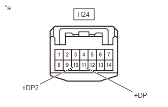
E383900C14
1.51,0.177 1.927,0.406 0.417,0.229 0.823,1.719 1.49,1.375 true 2.708,1.875 1.76,1.385 true 0.448,1.708 0.927,2.083 0.479,0.375 10 false +DP2 2.74,1.865 3.25,2.094 0.51,0.229 10 false +DP 0.094,0.073 0.573,0.448 0.479,0.375 10 false *a 1.583,0.208 1.99,0.406 0.406,0.198 10 false H24
*a Front view of wire harness connector
(to Spiral Cable Sub-assembly)


a.

Measure the voltage according to the value(s) in the table below.

Standard Voltage:
Tester Connection Condition Specified Condition
H24-10 (+DP2) - Body ground Ignition switch ON 4.8 to 5.2 V
H24-11 (+DP) - Body ground Ignition switch ON 4.8 to 5.2 V


Result:
Proceed to
OK
NG


OK

4.CONFIRM MODEL

NG

7.CHECK HARNESS AND CONNECTOR (SPIRAL CABLE SUB-ASSEMBLY - COMBINATION METER ASSEMBLY)
4.CONFIRM MODEL
a.

Choose the model to be inspected.


Result:
Result Proceed to
for 8 Inch Multi-display Type A
for 12.3 Inch Multi-display Type B


A

5.CHECK HARNESS AND CONNECTOR (RADIO AND DISPLAY RECEIVER ASSEMBLY - SPIRAL CABLE SUB-ASSEMBLY AND BODY GROUND)

B

6.CHECK HARNESS AND CONNECTOR (RADIO RECEIVER ASSEMBLY - SPIRAL CABLE SUB-ASSEMBLY AND BODY GROUND)
5.CHECK HARNESS AND CONNECTOR (RADIO AND DISPLAY RECEIVER ASSEMBLY - SPIRAL CABLE SUB-ASSEMBLY AND BODY GROUND)
a.

Disconnect the H1 radio and display receiver assembly connector.


b.

Measure the resistance according to the value(s) in the table below.

Standard Resistance:
Tester Connection Condition Specified Condition
H1-24 (SWG) - H24-4 (EAU) Always Below 1 Ω
H1-1 (GND1) - Body ground Always Below 1 Ω


Result:
Proceed to
OK
NG


OK

REPLACE RADIO AND DISPLAY RECEIVER ASSEMBLY

NG

REPAIR OR REPLACE HARNESS OR CONNECTOR

6.CHECK HARNESS AND CONNECTOR (RADIO RECEIVER ASSEMBLY - SPIRAL CABLE SUB-ASSEMBLY AND BODY GROUND)
a.

Disconnect the H4 radio receiver assembly connector.


b.

Measure the resistance according to the value(s) in the table below.

Standard Resistance:
Tester Connection Condition Specified Condition
H4-24 (SWG) - H24-4 (EAU) Always Below 1 Ω
H4-1 (GND1) - Body ground Always Below 1 Ω


Result:
Proceed to
OK
NG


OK

REPLACE RADIO RECEIVER ASSEMBLY

NG

REPAIR OR REPLACE HARNESS OR CONNECTOR

7.CHECK HARNESS AND CONNECTOR (SPIRAL CABLE SUB-ASSEMBLY - COMBINATION METER ASSEMBLY)
a.

Disconnect the H21 combination meter assembly connector.


b.

Measure the resistance according to the value(s) in the table below.

Standard Resistance:
Tester Connection Condition Specified Condition
H24-10 (+DP2) - H21-28 (MSM+) Always Below 1 Ω
H24-11 (+DP) - H21-29 (MSTI) Always Below 1 Ω
H24-10 (+DP2) or H21-28 (MSM+) - Body ground Always 10 kΩ or higher
H24-11 (+DP) or H21-29 (MSTI) - Body ground Always 10 kΩ or higher


Result:
Proceed to
OK
NG


OK

REPLACE COMBINATION METER ASSEMBLY

NG

REPAIR OR REPLACE HARNESS OR CONNECTOR