BRAKE (REAR) REAR BRAKE REMOVAL
CAUTION / NOTICE / HINT
The necessary procedures (adjustment, calibration, initialization, or registration) that must be performed after parts are removed and installed, or replaced during rear brake removal/installation are shown below.
| Replaced Part or Performed Procedure | Necessary Procedure | Effect/Inoperative Function when Necessary Procedure not Performed | Link |
|---|---|---|---|
|
*1: Learning can also be performed using the GTS. Click here( |
|||
| Auxiliary battery terminal is disconnected/reconnected | Perform steering sensor zero point calibration | Lane Control System | ( ) |
| Parking Support Brake System*1 | |||
| Pre-collision System | |||
| Memorize steering angle neutral point | Parking Assist Monitor System | ()
|
|
| Panoramic View Monitor System | ()
|
||
| Initialize back door lock | Power Door Lock Control System | ()
|
|
| Reset back door close position | Power Back Door System | ()
|
|
- NOTICE:
- ·
Immediately after installing the brake pads, the braking performance may be reduced. Always perform a road test in a safe place while paying attention to the surroundings.
·After replacing the rear disc brake pads, the brake pedal may feel soft due to clearance between the rear disc brake pads and rear disc. Depress the brake pedal several times until the brake pedal feels firm.
·After replacing the rear disc brake pads, always perform a road test to check the braking performance and check for vibrations.
·When removing or installing the rear disc brake cylinder assembly disc brake, pushing back the disc brake piston may cause a large clearance between the brake pads and brake disc. When the brake pedal is depressed with a large clearance between the brake pads and the brake disc, DTC C13DB00, C13DC00, C13DD00, C13DE00, C140000 and/or C140A00 related to abnormal brake fluid pressure may be stored. Make sure to clear any DTCs after performing this procedure. (for HV Model)
·While the auxiliary battery is connected, even if the ignition switch is off, the brake control system activates when the brake pedal is depressed or any door courtesy switch turns on. Therefore, when servicing the brake system components, do not operate the brake pedal or open/close the doors while the auxiliary battery is connected. (for HV Model)
·After the ignition switch is turned off, the radio and display receiver assembly or the radio receiver assembly records various types of memory and settings. As a result, after turning the ignition switch off, make sure to wait at least 120 seconds before disconnecting the cable from the negative (-) auxiliary battery terminal. (for HV Model)
- HINT:
- ·
Use the same procedure for the RH side and LH side.
·The following procedure is for the LH side.
PROCEDURE

 1. PRECAUTION
- NOTICE:
- ·
Make sure to read the precautions of the electric parking brake system before removing the rear brake assembly.
for HV Model: Click hereBrake>PARKING BRAKE>ELECTRIC PARKING BRAKE SYSTEM (for HV Model)>PRECAUTION
for Gasoline Model: Click hereBrake>PARKING BRAKE>ELECTRIC PARKING BRAKE SYSTEM (for Gasoline Model)>PRECAUTION
2.REMOVE REAR WHEEL
3.PERFORM REAR BRAKE PAD REPLACEMENT MODE
for HV Model: Click hereBrake>PARKING BRAKE>ELECTRIC PARKING BRAKE SYSTEM (for HV Model)>TEST MODE PROCEDURE
for Gasoline Model: Click hereBrake>PARKING BRAKE>ELECTRIC PARKING BRAKE SYSTEM (for Gasoline Model)>TEST MODE PROCEDURE
4.DISABLE BRAKE CONTROL (for HV Model)
Wait 4 minutes after turning the ignition switch off to ensure that the skid control ECU is in sleep mode.
- NOTICE:
- ·
When the brake pedal is depressed or the door courtesy switch is turned on even if the ignition switch is off, the brake control system activates. Therefore do not depress the brake pedal or open/close the doors until the reservoir level switch connector is disconnected.
·Do not operate the electric parking brake switch assembly when the electric parking brake system is in rear brake pad replacement mode.
for LHD:
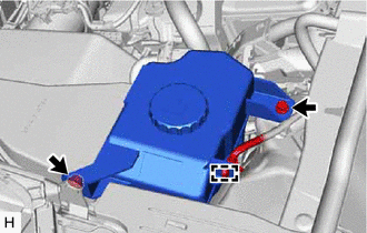
Disengage the clamp to separate the wire harness from the brake master cylinder reservoir assembly.
Remove the bolt and nut and separate the brake master cylinder reservoir assembly.
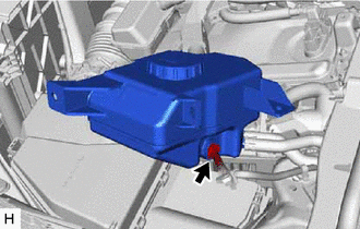
Disconnect the connector from the brake master cylinder reservoir assembly.
Return the brake master cylinder reservoir assembly to its original position.
- HINT:
-
Do this to prevent brake fluid leakage.
for RHD
Disconnect the connector from the brake master cylinder reservoir assembly.
Disconnect the cable from the negative (-) auxiliary battery terminal.
Click hereGeneral>MAINTENANCE>A25A-FXS, A25B-FXS AUXILIARY BATTERY>REMOVAL
In order to prevent pressurized brake fluid in the accumulator from being applied to the brake calipers, depress the brake pedal 40 times or more to return the pressurized brake fluid in the accumulator back to the brake master cylinder reservoir assembly.
Check that the brake pedal cannot be further depressed.
5.DRAIN BRAKE FLUID
- NOTICE:
-
If brake fluid leaks onto any painted surface, immediately wash it off.
47319F
6.SEPARATE REAR FLEXIBLE HOSE
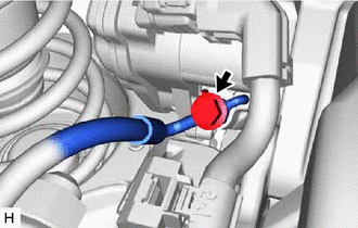
Remove the union bolt and gasket, and disconnect the rear flexible hose from the rear disc brake cylinder assembly.
890C0A
7.DISCONNECT NO. 2 PARKING BRAKE WIRE ASSEMBLY
46310B
8.REMOVE PARKING BRAKE ACTUATOR ASSEMBLY
47850
9.REMOVE REAR DISC BRAKE CYLINDER ASSEMBLY
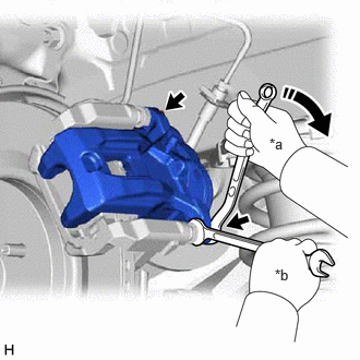
| *a | Turn |
| *b | Hold |
Hold the 2 rear disc brake cylinder slide pins and remove the 2 bolts and rear disc brake cylinder assembly.
04466
10.REMOVE REAR DISC BRAKE PAD
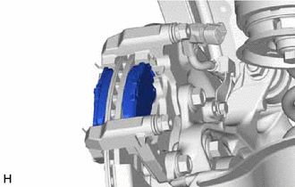
Remove the 2 rear disc brake pads from the rear disc brake cylinder mounting.
04946
11.REMOVE REAR DISC BRAKE ANTI-SQUEAL SHIM KIT
12.REMOVE REAR DISC BRAKE PAD SUPPORT PLATE
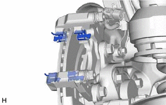
Remove the 4 rear disc brake pad support plates from the rear disc brake cylinder mounting.
- NOTICE:
-
Each rear disc brake pad support plate has a different shape. Be sure to put an identification mark on each rear disc brake pad support plate so that it can be reinstalled to its original position.
13.REMOVE REAR DISC BRAKE CYLINDER SLIDE PIN
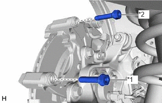
| *1 | Rear No. 1 Disc Brake Cylinder Slide Pin |
| *2 | Rear No. 2 Disc Brake Cylinder Slide Pin |
Remove the rear No. 1 disc brake cylinder slide pin and rear No. 2 disc brake cylinder slide pin from the rear disc brake cylinder mounting.
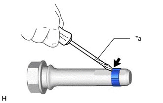
| *a | Protective Tape |
Using a screwdriver with its tip wrapped with protective tape, remove the rear disc brake cylinder slide bushing from the rear No. 2 disc brake cylinder slide pin.
- NOTICE:
-
Do not damage the rear No. 2 disc brake cylinder slide pin.
14.REMOVE REAR DISC BRAKE BUSHING DUST BOOT
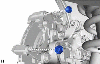
Remove the 2 rear disc brake bushing dust boots from the rear disc brake cylinder mounting.
47822
15.REMOVE REAR DISC BRAKE CYLINDER MOUNTING
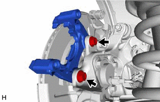
Remove the 2 bolts and rear disc brake cylinder mounting.
42431
16.REMOVE REAR DISC
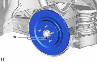
| *a | Matchmark |
Put matchmarks on the rear disc and rear axle hub and bearing assembly.
Remove the rear disc.