Fuel Injector
Fuel
COMPONENTS
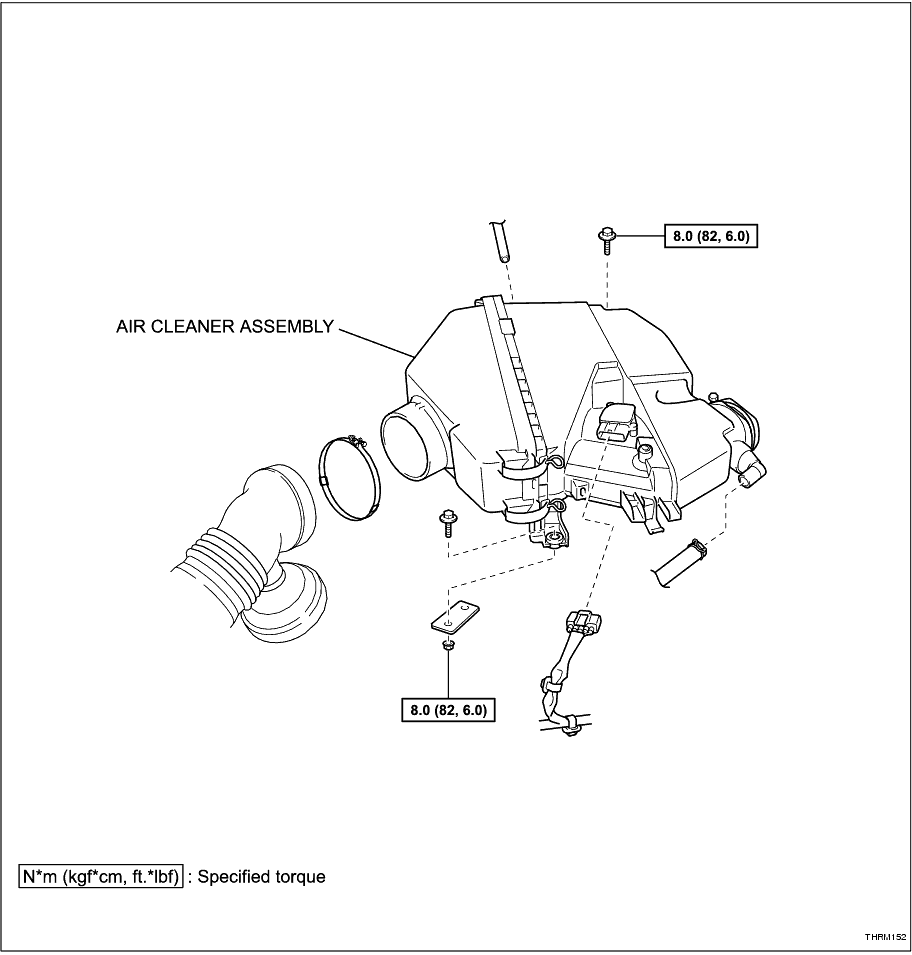
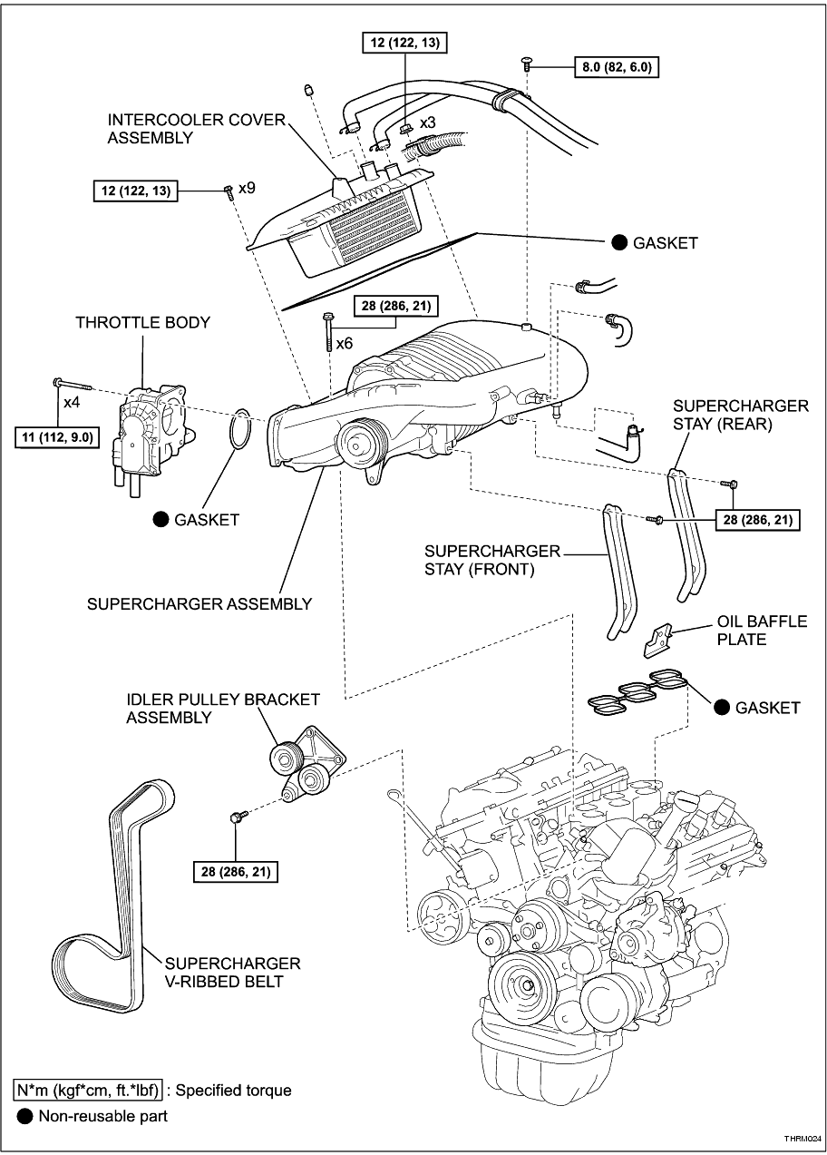
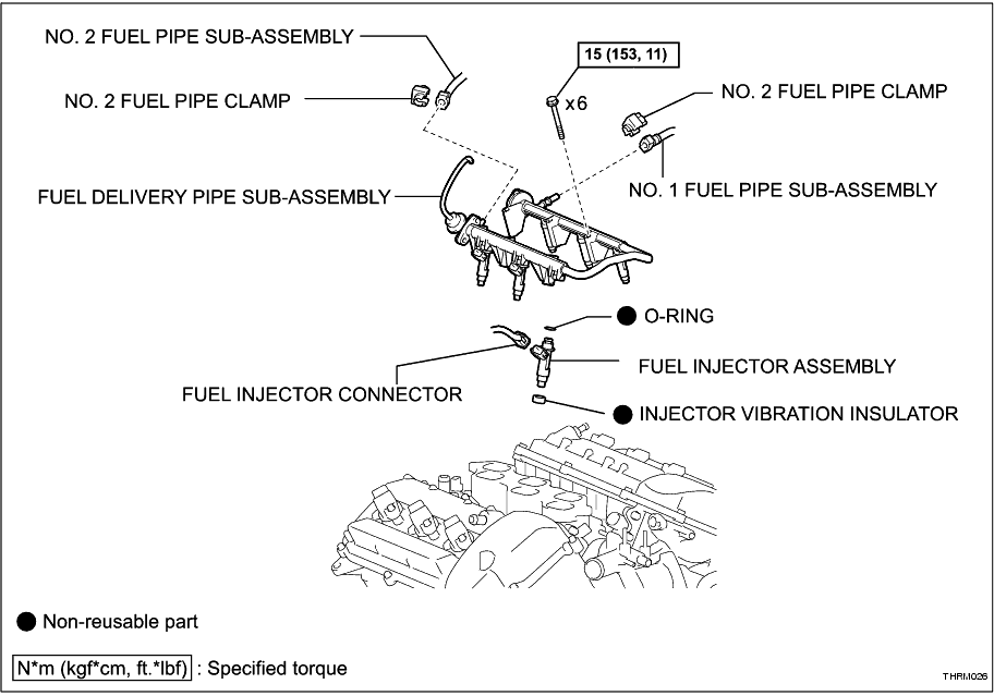
REMOVAL
1. DISCHARGE FUEL SYSTEM PRESSURE (
Click Here
)
2. DISCONNECT CABLE FROM NEGATIVE BATTERY TERMINAL
CAUTION:
Wait at least 90 seconds after disconnecting the cable from the negative (-) battery terminal to prevent airbag and seatbelt pretensioner activation.
HINT:
Obtain the audio system PIN from the vehicle owner, if applicable. Otherwise the audio system will be inoperable when the battery cable is reconnected.
3. DISCONNECT NO. 2 VENTILATION HOSE (
Click Here
)
4. REMOVE AIR CLEANER ASSEMBLY (
Click Here
)
5. DISCONNECT SUPERCHARGER V-RIBBED BELT (
Click Here
)
HINT:
Disconnect the belt from the supercharger puller only.
6. DISCONNECT VACUUM HOSES AND WIRING HARNESS (
Click Here
)
7. SEPARATE THROTTLE BODY (
Click Here
)
HINT:
To avoid draining the cooling system, remove the throttle body from the supercharger and place it to one side.
8. REMOVE SUPERCHARGER ASSEMBLY (
Click Here
)
HINT:
To avoid draining the intercooler cooling system, remove the supercharger cover with the hoses attached and move the cover to one side.
9. DISCONNECT NO. 1 FUEL PIPE SUB-ASSEMBLY
(a) Remove the fuel pipe clamp.
-
(b) Pinch the tube connector and then pull out the fuel pipe.
NOTICE:
• Check if there is any dirt or mud around the connector before this procedure, Clean if necessary. Foreign matter can affect the quick connector O-ring's seal between the fuel pipe and fuel delivery pipe.
• Do not use any tool in this procedure.
• Do not bend or twist the nylon tube.
• Keep the plug free from foreign objects.
• To protect the fuel pipe, cover it with a plastic bag after checking.
• When the fuel pipe and fuel delivery pipe are stuck, pinch the nylon tube with your fingers, and turn it carefully to free and then disconnect the fuel pipe.
-
10. DISCONNECT NO. 2 FUEL PIPE SUB-ASSEMBLY
(a) Remove the fuel pipe clamp.
-
(b) Pinch the tube connector and then pull out the fuel pipe.
NOTICE:
• Check if there is any dirt or mud around the connector before this procedure, Clean if necessary. Foreign matter can affect the quick connector O-ring's seal between the fuel pipe and fuel delivery pipe.
• Do not use any tool in this procedure.
• Do not bend or twist the nylon tube.
• Keep the plug free from foreign objects.
• To protect the fuel pipe, cover it with a plastic bag after checking.
• When the fuel pipe and fuel pressure regulator are stuck, pinch the nylon tube with fingers, and turn it carefully to free and then disconnect the fuel pipe.
-
11. REMOVE FUEL DELIVERY PIPE SUB-ASSEMBLY
(a) Disconnect the 6 fuel injector connectors.
-
(b) Remove the 6 bolts and fuel delivery pipe together with the 6 fuel injectors.
NOTICE:
Be careful not to drop the injectors when removing the fuel delivery pipe.
-
12. REMOVE INJECTOR ASSEMBLY
(a) Pull out the 6 injectors from the delivery pipe.
-
INSPECTION
1. INSPECT INJECTOR ASSEMBLY
(a) Check the injector resistance.
(1) Measure the resistance between the terminals.
Standard resistance:
11.6 to 12.4 ohms at 20°C (68°F)
If the result is not as specified, replace the injector assembly.
-
2. INSPECT INJECTION VOLUME AND LEAKAGE
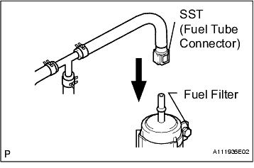
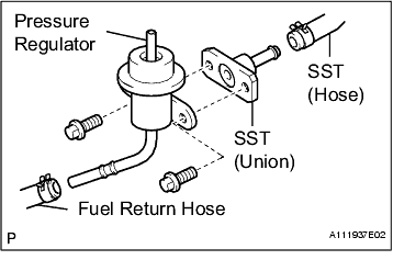
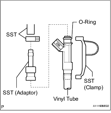
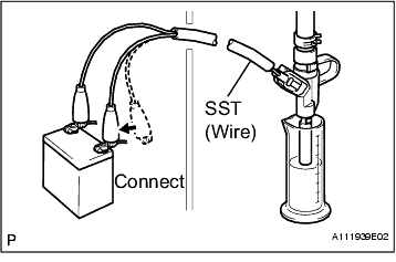
(a) Check the injection volume.
CAUTION:
• This test involves high-pressure fuel and electricity.
• Take every precaution regarding safe handling of both the fuel and the electrical parts.
• Perform this test in a safe area, and avoid any sparks or flame.
• Do not smoke.
(1) Assemble SST as shown in the illustration and described below.
SST
09268-31011
(09268-41091
09268-41110
09268-41120
09268-41400, 09268-41500
90467-13001, 95336-08070)
(2) Discharge the fuel system pressure.
(3) Disconnect the fuel inlet hose (fuel tube connector) from the fuel filter.
(4) Remove the bolt and disconnect the fuel pressure regulator from the fuel delivery pipe.
NOTICE:
Do not disconnect the fuel hose No. 2 from the fuel pressure regulator.
(5) Connect SST to the fuel filter.
CAUTION:
Always read the precautions before connecting the fuel tube connector.
(6) Connect the SST (hose) to the fuel inlet of the pressure regulator with another SST (union) and the 2 bolts.
(7) Connect the fuel return hose to the fuel outlet of the pressure regulator.
(8) Install the O-ring to the injector.
(9) Connect SST (adapter and hose) to the injector, and hold the injector and adapter with SST (clamp).
(10) Put the injector into a graduated cylinder.
HINT:
Install a suitable vinyl tube onto the injector to contain any gasoline spray.
(11) Operate the fuel pump by connecting the intelligent tester to the DLC3 and select Active Test / Fuel Pump.
(12) Connect SST (wire) to the injector and the battery for 15 seconds, and measure the injection volume with a graduated cylinder. Test each injector 2 or 3 times.
SST
09842-30080
Volume:
114 to 122 cm3 (6.9 to 7.4 cu in.) in 15 seconds
Difference between each injector:
8 cm3 (0.48 cu in.) or less
If the injection volume is not as specified, replace the injector.
NOTICE:
Always turn the voltage on and off on the battery side, not the fuel pump side.
If the result is not as specified, replace the injector assembly.
-
(b) Check the rate of fuel leakage.
(1) In the condition above, disconnect the test probes of SST (wire) from the battery and check the rate of fuel leakage from the injector.
Fuel leakage:
1 drop or less per 12 minutes
-
INSTALLATION
1. INSTALL INJECTOR ASSEMBLY
(a) Install a new insulator to each fuel injector.
-
(b) Apply a light coat of spindle oil or gasoline to a new O-ring and install it to each fuel injector.
-
(c) While turning the fuel injector left and right, install it to the fuel delivery pipe.
-
(d) Position the fuel injector connector outward.
-
2. INSTALL FUEL DELIVERY PIPE SUB-ASSEMBLY
(a) Place the fuel delivery pipe together with the 6 fuel injectors on the intake manifold.
-
(b) Temporarily install the 6 fuel delivery pipe bolts.
-
(c) Check the fuel injectors rotate smoothly.
HINT:
If the fuel injectors do not rotate smoothly, the probable cause is incorrect installation of O-ring. Replace the O-ring.
-
(d) Position the fuel injector connector outward.
-
(e) Tighten the 6 fuel delivery pipe bolts.
Torque:
15 N*m
(153 kgf*cm,
11 ft.*lbf)
-
(f) Connect the 6 fuel injector connectors.
-
3. CONNECT NO. 2 FUEL PIPE SUB-ASSEMBLY
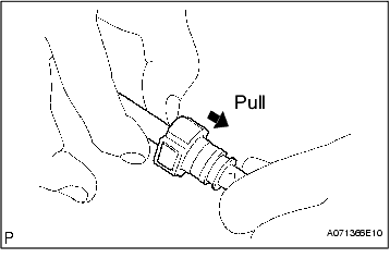
(a) Connect the fuel pipe.
(1) Check there is no damage or contamination in the connected part of the pipe.
(2) Align the axis of the connector with the axis of the pipe. Push the pipe into the connector until the connector makes a 'click' sound. If the connection is tight, apply a small amount of fresh engine oil on the tip of the pipe.
(3) After having finished the connection, try to pull apart the pipe and the connector and confirm they are securely connected.
-
(b) Install the fuel pipe clamp.
-
4. CONNECT NO. 1 FUEL PIPE SUB-ASSEMBLY
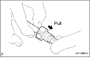
(a) Connect the fuel pipe.
(1) Check there is no damage or contamination in the connected part of the pipe.
(2) Align the axis of the connector with the axis of the pipe. Push the pipe into the connector until the connector makes a 'click' sound. If the connection is tight, apply a small amount of fresh engine oil on the tip of the pipe.
(3) After having finished the connection, try to pull apart the pipe and the connector and confirm they are securely connected.
-
(b) Install the fuel pipe clamp.
-
5. INSTALL SUPERCHARGER ASSEMBLY (
Click Here
)
6. INSTALL THROTTLE BODY (
Click Here
)
7. CONNECT VACUUM HOSES AND WIRING HARNESS (
Click Here
)
8. INSTALL SUPERCHARGER V-RIBBED BELT (
Click Here
)
9. INSTALL AIR CLEANER ASSEMBLY (
Click Here
)
10. CONNECT NO. 2 VENTILATION HOSE (
Click Here
)
11. CONNECT CABLE TO BATTERY NEGATIVE TERMINAL
12. CHECK FOR FUEL LEAKS
(a) Connect the intelligent tester to the DLC3.
(1) Turn the ignition switch ON.
NOTICE:
Do not start the engine.
(2) Push the intelligent tester main switch ON.
(3) Select Active Test and enter the following menus: Powertrain / Engine and ECT / Active Test / Control the Fuel Pump / Speed.
-
(b) Check for fuel leaks.
(1) Check there are no fuel leaks after performing maintenance anywhere on the fuel system.
-
13. PERFORM INITIALISATION
(a) Enter the audio system PIN, if applicable. Refer to Section 1-8 "Audio System" in the TRD Hilux Driver's Manual for programming information.
-
(b) Calibrate the multi-information display compass. Refer to Section 1-10 "Other Equipment" in the TRD Hilux Driver's Manual for calibrating information.
-