Supercharger Assembly
Supercharger
COMPONENTS
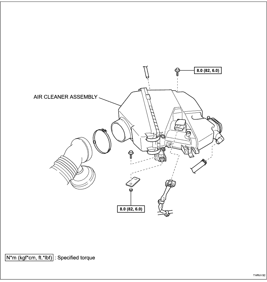
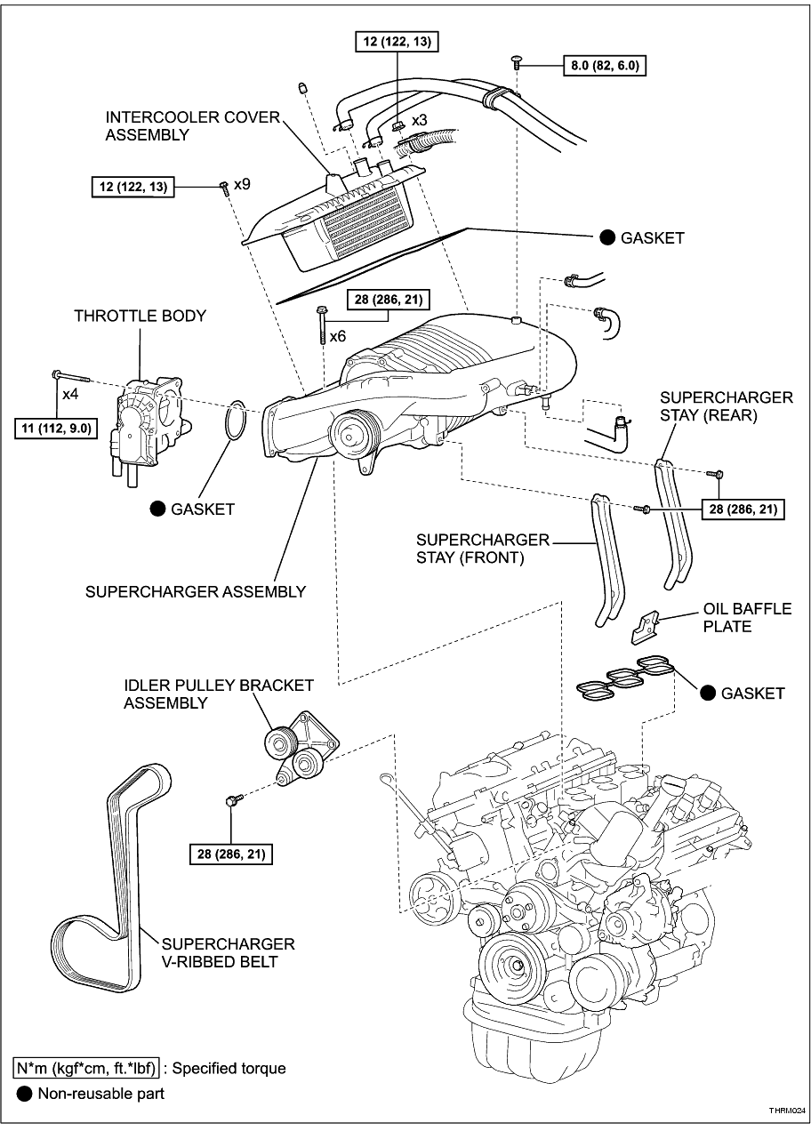
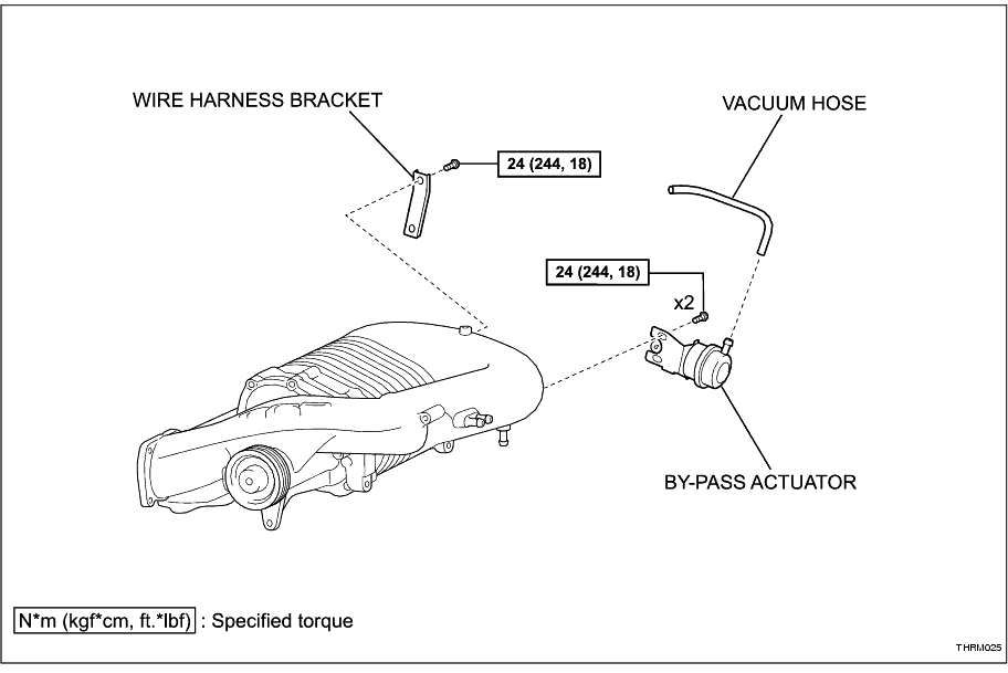
REMOVAL
1. DISCONNECT CABLE FROM BATTERY NEGATIVE TERMINAL
CAUTION:
Wait at least 90 seconds after disconnecting the cable from the negative (-) battery terminal to prevent airbag and seatbelt pretensioner activation.
HINT:
Obtain the audio system PIN from the vehicle owner, if applicable. Otherwise the audio system will be inoperable when the battery cable is reconnected.
2. DISCONNECT NO. 2 VENTILATION HOSE (
Click Here
)
3. REMOVE AIR CLEANER ASSEMBLY (
Click Here
)
4. DISCONNECT SUPERCHARGER V-RIBBED BELT (
Click Here
)
HINT:
Disconnect the belt from the supercharger puller only.
5. DISCONNECT VACUUM HOSES AND WIRING HARNESS
(a) Disconnect the brake booster vacuum hose (1).
-
(b) Disconnect the vacuum switching valve hose (2).
-
(c) Disconnect the ventilation valve hose (3).
-
(d) Unattach the wiring harness (4).
-
6. SEPARATE THROTTLE BODY
HINT:
To avoid draining the cooling system, do not remove the coolant hoses. Place the throttle body to the side.
(a) Disconnect the wire connector.
-
(b) Remove the 4 bolts and separate the throttle body from the supercharger and remove the gasket.
-
7. DISCONNECT INTERCOOLER COOLANT HOSES
HINT:
To avoid draining the intercooler cooling system, disconnect the intercooler coolant hoses only if the intercooler requires removal. As an alternative, remove the cover as described in the following steps with the hoses attached and move it to one side.
(a) Remove the screw attaching the hose clamp to the supercharger.
-
(b) Loosen the 2 clamps and remove the 2 intercooler coolant hoses.
-
8. REMOVE SUPERCHARGER ASSEMBLY
(a) Remove the 9 screws and 3 nuts and the supercharger intercooler cover assembly.
NOTICE:
Do not remove the screw between the coolant hose inlet and outlet; this attaches the intercooler to the cover.
HINT:
If the intercooler coolant hoses were not removed, move and secure the cover to one side.
-
(b) Remove the idler pulley bracket assembly (
Click Here
)
-
(c) Remove supercharger stays.
(1) Remove the bolt and the oil baffle plate.
(2) Remove the 4 bolts and the front and rear supercharger stays.
-
(d) Using SST, loosen the front supercharger to intake manifold bolt.
SST
SR-1143
-
(e) Loosen the 5 remaining bolts and remove the supercharger assembly.
-
(f) Remove the intake manifold gasket and discard.
NOTICE:
Cover the cylinder head inlet ports to prevent dirt from entering.
-
DISASSEMBLY
1. REMOVE INTERCOOLER ASSEMBLY (
Click Here
)
2. REMOVE BY-PASS ACTUATOR
(a) Disconnect the vacuum hose.
-
(b) Move the actuator lever and remove the lower screw.
-
(c) Remove the upper screw.
-
(d) Disconnect the actuator rod and remove the by-pass actuator.
-
3. REMOVE WIRING HARNESS BRACKET
(a) Remove the screw and wiring harness bracket.
-
4. REMOVE INTERCOOLER COVER STUDS
(a) Remove the 3 studs from the supercharger housing.
-
INSPECTION
1. INSPECT BY-PASS ACTUATOR
(a) Connect a vacuum pump to the by-pass actuator.
-
(c) Apply vacuum for 1 minute. The actuator should continue to remain open.
If the result is not as specified, replace the actuator assembly.
-
REASSEMBLY
1. INSTALL INTERCOOLER COVER STUDS
(a) Install the 3 studs into the supercharger housing.
Torque:
12 N*m
(122 kgf*cm,
13 ft.*lbf)
-
2. INSTALL WIRING HARNESS BRACKET
(a) Install the wiring harness bracket with the screw.
HINT:
Fit the screw to the small hole.
Torque:
24 N*m
(244 kgf*cm,
18 ft.*lbf)
-
3. INSTALL BY-PASS ACTUATOR
(a) Loosen the by-pass actuator stop screw.
-
(b) Connect the actuator rod to the lever.
HINT:
Ensure the lever is fitted between the 2 flats on the rod.
-
(c) Temporarily install the by-pass actuator with the 2 screws, ensuring it is correctly seated on the supercharger housing.
NOTICE:
Do not tighten the screws.
-
(d) Position the actuator with the lever in the fully closed (rest) position and with an even gap in the attaching screw slots.
-
(e) Tighten the 2 screws.
Torque:
20 N*m
(204 kgf*cm,
15 ft.*lbf)
-
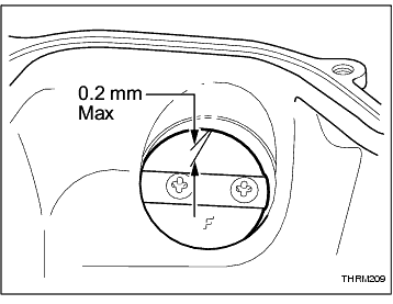
(f) Adjust the by-pass actuator stop screw.
(1) Adjust the stop screw until it touches the by-pass lever.
(2) Turn the stop screw one turn further.
(3) Tighten the lock nut securely.
(4) Manually operate the lever to fully open 3 times. Check the lever is still contacting the stop screw.
(5) Check by-pass valve operation by moving the lever by hand. Ensure the action is smooth and it does not bind.
(6) If the supercharger intercooler cover is not installed, inspect the by-pass valve plate. It should be fully seated in the bore with no more than a gap of 0.2 mm visible.
-
(g) Connect the vacuum hose.
-
4. INSTALL INTERCOOLER ASSEMBLY (
Click Here
)
INSTALLATION
1. INSTALL SUPERCHARGER ASSEMBLY
(a) Install the 6 bolts into the supercharger assembly. Screw the bolts completely through the supercharger housing.
-
(b) Install a new intake manifold gasket.
-
(c) Carefully install the supercharger assembly and start the 6 bolts.
NOTICE:
Do not tighten.
-
(d) Install supercharger stays.
(1) Install the front and rear supercharger stays with the 4 bolts.
NOTICE:
Do not tighten.
-
(e) Install idler pulley bracket assembly with the 3 bolts. (
Click Here
)
NOTICE:
Do not tighten.
-
(f) Tighten the 5 rear supercharger to intake manifold bolts.
Torque:
28 N*m
(286 kgf*cm,
21 ft.*lbf)
-
(g) Using SST, tighten the front supercharger to intake manifold bolt.
Torque:
28 N*m
(286 kgf*cm,
21 ft.*lbf)
SST
SR-1143
-
(h) Tighten the front and rear supercharger stay bolts.
Torque:
28 N*m
(286 kgf*cm,
21 ft.*lbf)
-
(i) Tighten the idler pulley bracket assembly bolts.
Torque:
28 N*m
(286 kgf*cm,
21 ft.*lbf)
-
(j) Install the oil baffle plate to the front supercharger stay with the bolt.
Torque:
5.0 N*m
(51 kgf*cm,
44 in.*lbf)
-
(k) Install a new gasket to the supercharger housing.
-
(l) Install the supercharger intercooler cover assembly with the 9 screws and 3 nuts.
HINT:
Attach the wiring clamps to the studs.
Torque:
12 N*m
(122 kgf*cm,
13 ft.*lbf)
-
2. CONNECT INTERCOOLER COOLANT HOSES
(a) If removed, fit the 2 intercooler coolant hoses with the clamps.
-
(b) Attach the hose clamp to the supercharger with the screw.
Torque:
8.0 N*m
(82 kgf*cm,
6.0 ft.*lbf)
-
3. INSTALL THROTTLE BODY
(a) Install a new throttle body gasket.
-
(b) Install the throttle body with the 4 bolts.
Torque:
11 N*m
(112 kgf*cm,
9.0 ft.*lbf)
-
(c) Connect the wire connector.
-
4. CONNECT VACUUM HOSES AND WIRING HARNESS
(a) Connect the brake booster vacuum hose (1).
-
(b) Connect the vacuum switching valve hose (2).
-
(c) Connect the ventilation valve hose (3).
-
(d) Attach the wiring harness (4).
-
5. INSTALL SUPERCHARGER V-RIBBED BELT (
Click Here
)
6. INSTALL AIR CLEANER ASSEMBLY (
Click Here
)
7. CONNECT NO. 2 VENTILATION HOSE (
Click Here
)
8. CONNECT CABLE TO NEGATIVE BATTERY TERMINAL
9. PERFORM INITIALISATION
(a) Enter the audio system PIN, if applicable. Refer to Section 1-8 "Audio System" in the TRD Hilux Driver's Manual for programming information.
-
(b) Calibrate the multi-information display compass. Refer to Section 1-10 "Other Equipment" in the TRD Hilux Driver's Manual for calibrating information.
-