| B |  |
| REPAIR OR REPLACE MALFUNCTIONING PARTS |
ECD SYSTEM (w/ EGR Cooler) > Engine Knocking or Rattling |
| Malfunction Condition | Main Trouble Area | Related Trouble Area |
|
|
|
| 1.CHECK SOUND AREA |
Find the source of the abnormal sound using a mechanic's stethoscope.
| Result | Proceed to |
| Combustion noise from engine | A |
| Noise from specific part | B |
|
| ||||
| A | |
 |
| 2.CHECK HARNESS AND CONNECTOR IN ENGINE COMPARTMENT |
Check the harness and connector connections of common rail system components.
|
| ||||
| OK | |
|
| 3.CHECK AIR INDUCTION SYSTEM (PROCEDURE 3) |
Check the air induction system (turbocharger, MAP sensor, EGR valve etc.).
|
| ||||
| OK | |
|
| 4.READ DTCS OUTPUT (RELATING TO ENGINE) |
Connect the intelligent tester to the DLC3.
Turn the ignition switch to ON and turn the tester on.
Enter the following menus: Powertrain / Engine and ECT / DTC.
Read DTCs.
| Result | Proceed to |
| No output | A |
| Engine related DTCs | B |
|
| ||||
| A | |
|
| 5.READ VALUE USING INTELLIGENT TESTER (MAP AND ATMOSPHERE PRESSURE) |
Connect the intelligent tester to the DLC3.
Turn the ignition switch to ON and turn the tester on.
Enter the following menus: Powertrain / Engine and ECT / Data List / MAP and Atmosphere Pressure.
Compare MAP to Atmosphere Pressure when the ignition switch is ON (do not start the engine).
| Result | Proceed to |
| MAP and Atmosphere Pressure have the same value | A |
| MAP is different from actual atmospheric pressure | B |
| Atmosphere Pressure is different from actual atmospheric pressure | C |
|
| ||||
|
| ||||
| A | |
|
| 6.PERFORM ACTIVE TEST USING INTELLIGENT TESTER (TEST THE FUEL LEAK) |
Connect the intelligent tester to the DLC3.
Turn the ignition switch to ON and turn the tester on.
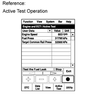 |
Enter the following menus: Powertrain / Engine and ECT / Active Test / Test the Fuel Leak / Data List / Fuel Press, Target Common Rail Pressure, and Target Pump SCV Current.
Take a snapshot with the intelligent tester during the Active Test.
Measure the difference between the target fuel pressure (Target Common Rail Pressure) and the actual fuel pressure (Fuel Press) when the "Test the Fuel Leak" Active Test is performed.
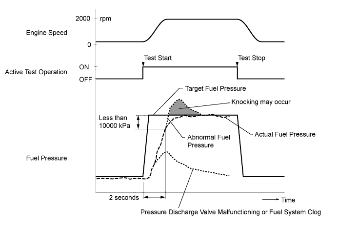
Read the value of Target Pump SCV Current in the Data List when the "Test the Fuel Leak" Active Test is performed.
| Result | Proceed to |
| Both results are within standard range | A |
| Fuel pressure exceeds "Target Common Rail Pressure + 15000 kPa" and/or Target Pump SCV Current value is out of standard range | B |
| Fuel pressure does not reach "Target Common Rail Pressure - 15000 kPa" within 2 seconds | C |
|
| ||||
|
| ||||
| A | |
|
| 7.CHECK INJECTOR COMPENSATION CODE |
Check the injector compensation code .
|
| ||||
| OK | |
|
| 8.RESET ECM |
Disconnect the cable from the negative (-) battery terminal for at least 2 minutes.
Reconnect the cable to the negative (-) battery terminal.
Check whether the malfunction has been successfully repaired.
|
| ||||
| OK | ||
 | ||
| ||
| 9.READ VALUE USING INTELLIGENT TESTER (ACTIVATE THE VSV FOR EGR CUT) |
Connect the intelligent tester to the DLC3.
Start the engine and warm it up (engine coolant temperature is 70°C (158°F) or higher), and the A/C switch and all accessory switches should be off.
Turn the ignition switch off. Wait for 30 seconds and then restart the engine.
Turn the tester on.
Select the following menus: Powertrain / Engine and ECT / Data List / MAF.
Read the MAF value displayed on the tester when engine idling.
Select the following menus: Powertrain / Engine and ECT / Active Test / Activate The VSV for EGR Cut.
Read the MAF value when the VSV for EGR cut is turned from off to on using the Active Test function.
| Active Test | Result | Proceed to |
| Activate The VSV for EGR Cut: off (Open) to on (Close) | MAF value is not changed | B |
| MAF value is changed | A |
| EGR Valve Condition (Opening) | MAF (Reference) | Measuring Condition |
| Open | 3.0 to 9.0 g/sec |
|
| Close | 15 to 22 g/sec |
|
| ||||
| A | |
|
| 10.READ VALUE USING INTELLIGENT TESTER (EGR CLOSE LEARN VAL. AND EGR CLOSE LRN. STATUS) |
Turn the ignition switch to ON.
Turn the ignition switch to off, and wait for 15 seconds or more.
Connect the intelligent tester to the DLC3.
Turn the ignition switch to ON and turn the tester on.
Enter the following menus: Powertrain / Engine and ECT / Data List / EGR Close Learn Val. and EGR Close Lrn. Status.
Read the values.
|
| ||||
| OK | |
|
| 11.INSPECT DIESEL THROTTLE BODY ASSEMBLY |
Inspect the diesel throttle body assembly (using intelligent tester).
Turn the ignition switch to ON.
Turn the ignition switch to off and wait for 5 seconds or more.
Connect the intelligent tester to the DLC3.
Turn the ignition switch to ON and turn the tester on.
Enter the following menus: Powertrain / Engine and ECT / Data List / Actual Throttle Position.
Read the values.
| Engine Condition | Specified Condition |
| Ignition switch ON | -5 to 5% |
| Idling (after engine warmed up, at an altitude near sea level) | 55 to 90% |
| Accelerator pedal fully depressed | -5 to 5% and value changes smoothly in transition |
| Throttle Valve Condition | Actual Throttle Position |
| Fully closed | 100% |
| Fully open | 0% |
Enter the following menus: Powertrain / Engine and ECT / Data List / Throttle Close Learning Val. and Diesel Throttle Learn Status.
Read the values when the ignition switch is ON.
Inspect the diesel throttle body assembly (does not use intelligent tester).
Inspect throttle valve operation visually.
|
| ||||
| OK | |
|
| 12.CHECK THE TEMPERATURE WHEN KNOCKING OCCURS |
Check the temperature when knocking trouble occurs.
| Result | Proceed to |
| Knocking only for cold engine | A |
| Knocking both for cold and warmed up engine | B |
|
| ||||
| A | |
|
| 13.CHECK ENGINE COOLANT TEMPERATURE SENSOR |
After warming up the engine, the engine coolant temperature should be 70°C (158°F) or more. After leaving the vehicle overnight, the engine coolant temperature should be nearly equal to the intake air temperature.
|
| ||||
| OK | |
|
| 14.INSPECT GLOW PLUG ASSEMBLY (RESISTANCE) |
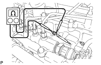 |
Disconnect the glow plug connector.
Measure the resistance according to the value(s) in the table below.
| Tester Connection | Condition | Specified Condition |
| Glow plug terminal - Body ground | 20°C (68°F) | Approximately 0.95 Ω |
|
| ||||
| OK | |
|
| 15.READ VALUE USING INTELLIGENT TESTER (INJECTION FEEDBACK VAL #1 TO #4) |
Connect the intelligent tester to the DLC3.
Turn the ignition switch to ON and the tester on.
Enter the following menus: Powertrain / Engine and ECT / Data List / Injector Feedback Val. #1 to #4.
Start the engine.
Read the values during engine idling when it is cold, and write them down.
| Tester Display | Condition | Specified Condition |
| Injector Feedback Val. #1 Injector Feedback Val. #2 Injector Feedback Val. #3 Injector Feedback Val. #4 | Idling with cold engine | Between -3.0 and 3.0 mm3/st |
|
| ||||
| OK | |
|
| 16.READ VALUE USING INTELLIGENT TESTER (MAP AND MAF) |
Connect the intelligent tester to the DLC3.
Turn the ignition switch to ON and the tester on.
Enter the following menus: Powertrain / Engine and ECT / Data List / MAP and MAF.
| Item | Engine Speed*1 | Standard Range | Description |
| MAP*2 | Ignition switch ON (engine stopped) | Same as atmospheric pressure | Intake manifold internal pressure detected by manifold absolute pressure sensor |
| Idling | 95 to 105 kPa (713 to 788 mmHg, 28.05 to 31.01 in.Hg) | ||
| 3000 rpm (no engine load) | 100 to 130 kPa (750 to 975 mmHg, 29.53 to 38.39 in.Hg) | ||
| 3500 rpm (driving with full throttle acceleration) | Min.: 180 kPa (1350 mmHg, 53.15 in.Hg) | ||
| MAF*2, *3 | Ignition switch ON (engine stopped) | Less than 0.35 g/s | Intake air volume detected by mass air flow meter |
| Idling | 5 to 12 g/s | ||
| 3000 rpm (no engine load) | 45 to 65 g/s | ||
| 3500 rpm (driving with full throttle acceleration) | Min.: 150 g/s |
| Item | Result | Proceed to |
| MAP and MAF | Within standard range | A |
| MAP and MAF | Outside standard range | B |
| Only MAP | Outside standard range | C |
| Only MAF | Outside standard range | D |
|
| ||||
|
| ||||
|
| ||||
| A | |
|
| 17.INSPECT EGR VALVE ASSEMBLY |
Remove the EGR valve assembly.
Check that the EGR valve is fully closed.
|
| ||||
| OK | |
|
| 18.BASIC INSPECTION |
Check the fuel quality.
Check the fuel for air.
Check the fuel system for blockages.
Check the air filter.
Check the engine oil.
Check the engine idling speed and the maximum engine speed.
Check the vacuum pump.
|
| ||||
| OK | |
|
| 19.CONFIRM WHETHER MALFUNCTION HAS BEEN SUCCESSFULLY REPAIRED |
Check whether the knocking has been successfully repaired.
|
| ||||
| OK | ||
| ||
| ||
| 20.READ VALUE USING INTELLIGENT TESTER (INJECTION VOLUME AND INJECTION FEEDBACK VAL #1 TO #4) |
Connect the intelligent tester to the DLC3.
Start the engine and warm it up until the engine coolant temperature reaches 75°C (167°F) or higher.
Allow the engine to idle for 1 minute or more.
Turn the tester on.
Enter the following menus: Powertrain / Engine and ECT / Data List / Injection Volume and Injector Feedback Val. #1 to #4.
Read the values during engine idling.
| Tester Display | Condition | Specified Condition |
| Injection Volume | Idling | Less than 10.0 mm3/st |
| Injector Feedback Val. #1 Injector Feedback Val. #2 Injector Feedback Val. #3 Injector Feedback Val. #4 | Idling | Between -3.0 and 3.0 mm3/st |
|
| ||||
| OK | ||
| ||
| ||
| 21.BLEED AIR FROM FUEL SYSTEM |
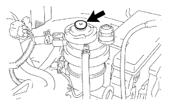 |
Using the hand pump mounted on the fuel filter cap, bleed the air from the fuel system. Continue pumping until the pump resistance increases.
Start the engine.
When the engine can be started, proceed to the next step.
If the engine cannot be started, bleed the air again using the hand pump until the hand pump resistance increases. Then start the engine.
Turn the ignition switch off.
Connect the intelligent tester to the DLC3.
Turn the ignition switch to ON and turn the tester ON.
Start the engine.
Enter the following menus: Powertrain / Engine and ECT / Active Test / Test the Fuel Leak.
|
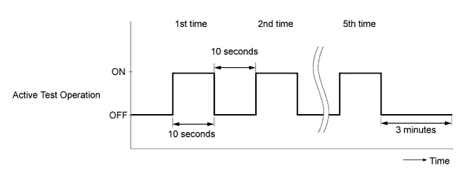
Perform the following test 5 times with on/off intervals of 10 seconds: Active Test / Test the Fuel Leak.
Allow the engine to idle for 3 minutes or more after performing the Active Test for the fifth time.
| NEXT | |
|
| 22.PERFORM ACTIVE TEST USING INTELLIGENT TESTER (FUEL LEAK TEST) |
Connect the intelligent tester to the DLC3.
Turn the ignition switch to ON and turn the tester on.
|
Enter the following menus: Powertrain / Engine and ECT / Active Test / Test the Fuel Leak / Data List / Fuel Press, Target Common Rail Pressure, and Target Pump SCV Current.
Take a snapshot with the intelligent tester during the Active Test.
Measure the difference between the target fuel pressure (Target Common Rail Pressure) and the actual fuel pressure (Fuel Press) when the "Test the Fuel Leak" Active Test is performed.
|
| ||||
| OK | |
|
| 23.CONFIRM WHETHER MALFUNCTION HAS BEEN SUCCESSFULLY REPAIRED |
Check whether the knocking has been successfully repaired.
| NEXT | ||
| ||
| ||
| 24.CONFIRM IF FUEL BEING SUPPLIED TO FUEL SUPPLY PUMP |
Disconnect the inlet hose from the fuel supply pump.
Operate the hand pump and check that fuel is being supplied to the fuel supply pump.
|
| ||||
| OK | |
|
| 25.REPLACE SUPPLY PUMP ASSEMBLY |
Replace the fuel supply pump assembly (Click here).
| NEXT | |
|
| 26.BLEED AIR FROM FUEL SYSTEM |
Bleed the air from the fuel system .
| NEXT | |
|
| 27.PERFORM FUEL SUPPLY PUMP INITIALIZATION |
Perform fuel supply pump initialization (Click here).
| NEXT | |
|
| 28.PERFORM ACTIVE TEST USING INTELLIGENT TESTER (FUEL LEAK TEST) |
Connect the intelligent tester to the DLC3.
Turn the ignition switch to ON and turn the tester on.
|
Enter the following menus: Powertrain / Engine and ECT / Active Test / Test the Fuel Leak / Data List / Fuel Press, Target Common Rail Pressure, and Target Pump SCV Current.
Take a snapshot with the intelligent tester during the Active Test.
Measure the difference between the target fuel pressure (Target Common Rail Pressure) and the actual fuel pressure (Fuel Press) when the "Test the Fuel Leak" Active Test is performed.
| Result | Proceed to |
| Outside standard range | A |
| Within standard range | B |
|
| ||||
| A | |
|
| 29.REPLACE COMMON RAIL ASSEMBLY |
Replace the common rail assembly (Click here).
| NEXT | |
|
| 30.BLEED AIR FROM FUEL SYSTEM |
Bleed the air from the fuel system .
| NEXT | |
|
| 31.CONFIRM WHETHER MALFUNCTION HAS BEEN SUCCESSFULLY REPAIRED |
Check whether the knocking has been successfully repaired by starting the engine.
| NEXT | ||
| ||
| ||
| 32.REPLACE FUEL INJECTOR ASSEMBLY |
Replace all of the fuel injector assembly (Click here).
| NEXT | |
|
| 33.REGISTER INJECTOR COMPENSATION CODE AND PERFORM PILOT QUANTITY LEARNING |
Register the injector compensation code .
Perform the fuel injector pilot quantity learning .
| NEXT | |
|
| 34.BLEED AIR FROM FUEL SYSTEM |
Bleed the air from the fuel system .
| NEXT | |
|
| 35.CONFIRM WHETHER MALFUNCTION HAS BEEN SUCCESSFULLY REPAIRED |
Check whether the knocking has been successfully repaired by starting the engine.
| NEXT | ||
| ||
| ||
