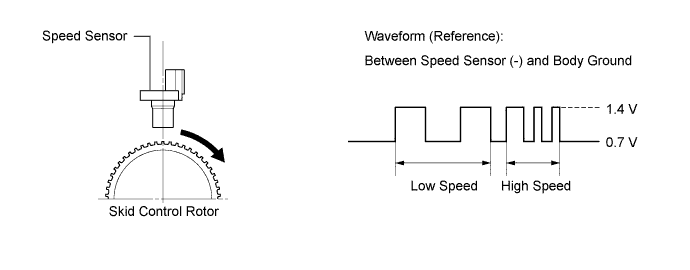
DTC C0210/33 Rear Speed Sensor RH Circuit |
DTC C0215/34 Rear Speed Sensor LH Circuit |
DTC C1273/73 Low Output Signal of Rear Speed Sensor RH (Test Mode DTC) |
DTC C1274/74 Low Output Signal of Rear Speed Sensor LH (Test Mode DTC) |
| DTC Code | DTC Detection Condition | Trouble Area |
| C0210/33 C0215/34 | When one of the following conditions is met:
|
|
| C1273/73 C1274/74 | Detected only during Test Mode. |
|
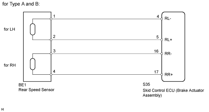
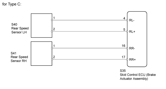
| 1.CHECK HARNESS AND CONNECTOR (MOMENTARY INTERRUPTION) |
Using the intelligent tester, check for any momentary interruption in the wire harnesses and connectors corresponding to the DTC (Click here).
| Tester Display | Measurement Item/Range | Normal Condition | Diagnostic Note |
| RR Speed Open | Rear speed sensor RH open detection / Error or Normal | Normal | - |
| RL Speed Open | Rear speed sensor LH open detection / Error or Normal | Normal | - |
|
| ||||
| OK | |
 |
| 2.READ VALUE USING INTELLIGENT TESTER (REAR SPEED SENSOR) |
Turn the ignition switch off.
Connect the intelligent tester to the DLC3.
Start the engine.
Select the Data List mode on the intelligent tester (Click here).
| Tester Display | Measurement Item/Range | Normal Condition | Diagnostic Note |
| RR Wheel Speed | Rear wheel RH speed sensor reading / min.: 0 km/h (0 mph), max.: 326 km/h (202 mph) | Actual wheel speed | Similar to speed indicated on speedometer |
| RL Wheel Speed | Rear wheel LH speed sensor reading / min.: 0 km/h (0 mph), max.: 326 km/h (202 mph) | Actual wheel speed | Similar to speed indicated on speedometer |
Check that there is no significant difference between the speed value displayed on the intelligent tester and the speed value displayed on the speedometer when driving the vehicle.
|
| ||||
| OK | |
|
| 3.PERFORM TEST MODE (SIGNAL CHECK) |
Perform the sensor check in the Test Mode procedure (Click here).
|
| ||||
| OK | |
|
| 4.RECONFIRM DTC |
Clear the DTC(s) (Click here).
Start the engine.
Drive the vehicle at a speed of 40 km/h (25 mph) or more for at least 60 seconds.
Check if the same DTC is recorded (Click here).
| Result | Proceed to |
| DTC not output | A |
| DTC output | B |
|
| ||||
| A | ||
 | ||
| ||
| 5.CHECK IF SKID CONTROL ECU AND REAR SPEED SENSOR CONNECTORS ARE SECURELY CONNECTED |
Check if the skid control ECU and rear speed sensor connectors are securely connected.
| NEXT | |
|
| 6.RECONFIRM DTC |
Clear the DTC(s) (Click here).
Start the engine.
Drive the vehicle at a speed of 40 km/h (25 mph) or more for at least 60 seconds.
Check if the same DTC is recorded (Click here).
| Result | Proceed to |
| DTC output | A |
| DTC not output | B |
|
| ||||
| A | |
|
| 7.CHECK REAR SPEED SENSOR INSTALLATION |
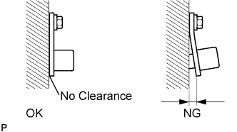 |
Turn the ignition switch off.
Check the speed sensor installation (Click here).
|
| ||||
| OK | |
|
| 8.CHECK REAR SPEED SENSOR TIP |
Remove the rear speed sensor (Click here).
Check the speed sensor tip.
|
| ||||
| OK | |
|
| 9.INSPECT REAR SPEED SENSOR |
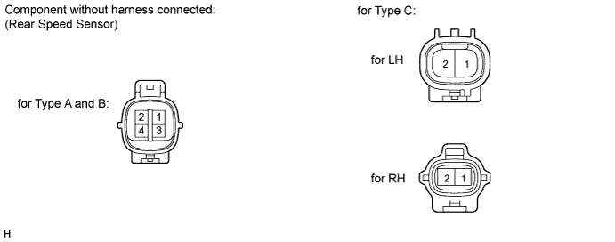
for Type A and B:
Disconnect the BE1 rear speed sensor connector.
for Type C:
Disconnect the S40 and/or S41 rear speed sensor connector.
Measure the resistance according to the value(s) in the table below.
| Tester Connection | Condition | Specified Condition |
| 1 - Body ground | Always | 10 kΩ or higher |
| 2 - Body ground | Always | 10 kΩ or higher |
| 1 - 3 | Always | 10 kΩ or higher |
| 1 - 4 | Always | 10 kΩ or higher |
| 2 - 3 | Always | 10 kΩ or higher |
| 2 - 4 | Always | 10 kΩ or higher |
| Tester Connection | Condition | Specified Condition |
| 3 - Body ground | Always | 10 kΩ or higher |
| 4 - Body ground | Always | 10 kΩ or higher |
| 1 - 3 | Always | 10 kΩ or higher |
| 1 - 4 | Always | 10 kΩ or higher |
| 2 - 3 | Always | 10 kΩ or higher |
| 2 - 4 | Always | 10 kΩ or higher |
| Tester Connection | Condition | Specified Condition |
| 1 - Body ground | Always | 10 kΩ or higher |
| 2 - Body ground | Always | 10 kΩ or higher |
|
| ||||
| OK | |
|
| 10.CHECK HARNESS AND CONNECTOR (SKID CONTROL ECU - REAR SPEED SENSOR) |
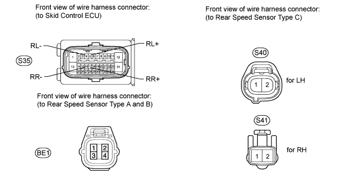
Disconnect the skid control ECU connector.
for Type A and B:
Disconnect the BE1 rear speed sensor connector.
for Type C:
Disconnect the S40 and/or S41 rear speed sensor connector.
Measure the resistance according to the value(s) in the table below.
| Tester Connection | Condition | Specified Condition |
| S35-5 (RL+) - BE1-2 | Always | Below 1 Ω |
| S35-4 (RL-) - BE1-1 | Always | Below 1 Ω |
| BE1-2 - Body ground | Always | 10 kΩ or higher |
| BE1-1 - Body ground | Always | 10 kΩ or higher |
| BE1-1 - BE1-2 | Always | 10 kΩ or higher |
| BE1-1 - BE1-3 | Always | 10 kΩ or higher |
| BE1-1 - BE1-4 | Always | 10 kΩ or higher |
| BE1-2 - BE1-3 | Always | 10 kΩ or higher |
| BE1-2 - BE1-4 | Always | 10 kΩ or higher |
| Tester Connection | Condition | Specified Condition |
| S35-17 (RR+) - BE1-4 | Always | Below 1 Ω |
| S35-16 (RR-) - BE1-3 | Always | Below 1 Ω |
| BE1-4 - Body ground | Always | 10 kΩ or higher |
| BE1-3 - Body ground | Always | 10 kΩ or higher |
| BE1-3 - BE1-4 | Always | 10 kΩ or higher |
| BE1-3 - BE1-1 | Always | 10 kΩ or higher |
| BE1-3 - BE1-2 | Always | 10 kΩ or higher |
| BE1-4 - BE1-1 | Always | 10 kΩ or higher |
| BE1-4 - BE1-2 | Always | 10 kΩ or higher |
| Tester Connection | Condition | Specified Condition |
| S35-5 (RL+) - S40-2 | Always | Below 1 Ω |
| S35-4 (RL-) - S40-1 | Always | Below 1 Ω |
| S40-2 - Body ground | Always | 10 kΩ or higher |
| S40-1 - Body ground | Always | 10 kΩ or higher |
| Tester Connection | Condition | Specified Condition |
| S35-17 (RR+) - S41-2 | Always | Below 1 Ω |
| S35-16 (RR-) - S41-1 | Always | Below 1 Ω |
| S41-2 - Body ground | Always | 10 kΩ or higher |
| S41-1 - Body ground | Always | 10 kΩ or higher |
|
| ||||
| OK | |
|
| 11.INSPECT SKID CONTROL ECU (SENSOR INPUT) |
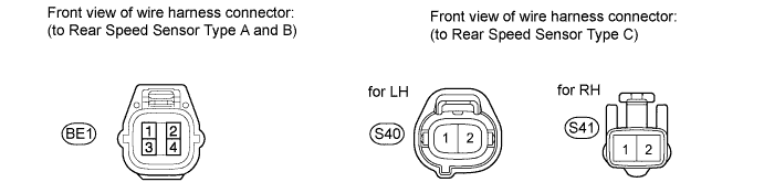
for Type A and B:
Disconnect the BE1 rear speed sensor connector.
for Type C:
Disconnect the S40 and/or S41 rear speed sensor connector.
Measure the voltage according to the value(s) in the table below.
| Tester Connection | Switch Condition | Specified Condition |
| BE1-2 - Body ground | Ignition switch ON | 8 to 14 V |
| Tester Connection | Switch Condition | Specified Condition |
| BE1-4 - Body ground | Ignition switch ON | 8 to 14 V |
| Tester Connection | Switch Condition | Specified Condition |
| S40-2 - Body ground | Ignition switch ON | 8 to 14 V |
| Tester Connection | Switch Condition | Specified Condition |
| S41-2 - Body ground | Ignition switch ON | 8 to 14 V |
|
| ||||
| OK | |
|
| 12.REPLACE REAR SPEED SENSOR |
Turn the ignition switch off.
Replace the rear speed sensor (Click here).
| NEXT | |
|
| 13.RECONFIRM DTC |
Clear the DTC(s) (Click here).
Start the engine.
Drive the vehicle at a speed of 40 km/h (25 mph) or more for at least 60 seconds.
Check if the same DTC is recorded (Click here).
| Result | Proceed to |
| DTC output | A |
| DTC not output | B |
|
| ||||
| A | |
|
| 14.REPLACE REAR SKID CONTROL ROTOR |
Turn the ignition switch off.
Replace the rear skid control rotor (Click here).
| NEXT | |
|
| 15.RECONFIRM DTC |
Clear the DTC(s) (Click here).
Start the engine.
Drive the vehicle at a speed of 40 km/h (25 mph) or more for at least 60 seconds.
Check if the same DTC is recorded (Click here).
| Result | Proceed to |
| DTC not output | A |
| DTC output | B |
|
| ||||
| A | ||
| ||
| ||

