REMOVE OPTIONAL COMPONENTS AND CHECK AGAIN (SEE NOTICE ABOVE)
3. CHECK RADIO ANTENNA
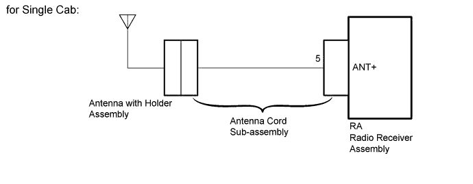
for Single Cab:
Remove the antenna with holder assembly from the antenna cord sub-assembly (Click here).
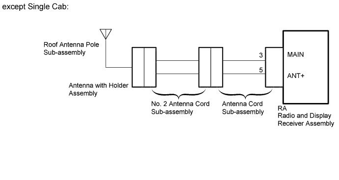
except Single Cab:
Remove the roof antenna pole sub-assembly from the amplifier antenna assembly (Click here).
Turn the ignition switch to ACC with the radio and display receiver assembly connector connected.
Place a screwdriver, thin wire or other metal object on the amplifier antenna threaded installation position for the antenna with holder assembly (for Single Cab) or roof antenna pole sub-assembly (except Single Cab), and check that noise can be heard from the speakers.
REPLACE RADIO AND DISPLAY RECEIVER ASSEMBLY (Click here)
4. CHECK RADIO AND DISPLAY RECEIVER ASSEMBLY (ANTENNA)
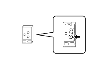
Remove the antenna connector from the radio and display receiver assembly.
Turn the ignition switch to ACC with the radio and display receiver assembly connector connected.
Turn on the radio and turn into AM mode.
Place a screwdriver, thin wire or other metal object on the radio and display receiver assembly antenna jack and check that noise can be heard from the speakers.
OK:
Noise occurs.
NG
REPLACE RADIO AND DISPLAY RECEIVER ASSEMBLY (Click here)
OK
5. INSPECT RADIO AND DISPLAY RECEIVER ASSEMBLY
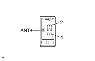
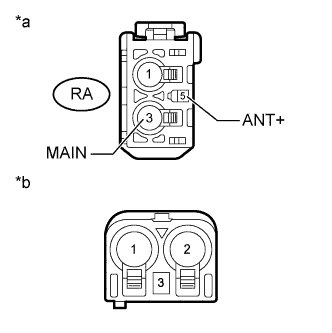
Disconnect the RA radio and display receiver assembly connector.
Measure the voltage according to the value(s) in the table below.
Standard Voltage:
Tester Connection
Switch Condition
Specified Condition
5 (ANT+) - Body ground
Ignition switch ACC, radio switch on and FM or AM selected