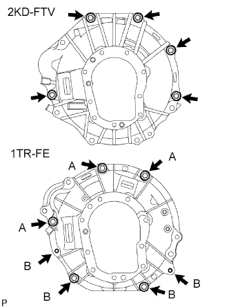
Align the input shaft with the clutch disc and install the transmission to the engine.
2KD-FTV: Install the 5 bolts.
Torque:
72 N*m{
730 kgf*cm
, 53 ft.*lbf
}
1TR-FE: Install the 7 bolts.
Torque:
72 N*m{
730 kgf*cm
, 53 ft.*lbf
}
for bolt A
37 N*m{
377 kgf*cm
, 27 ft.*lbf
}
for bolt B
2.
INSTALL STIFFENER PLATE (2KD-FTV)
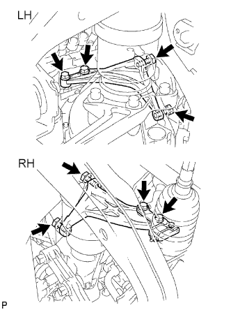
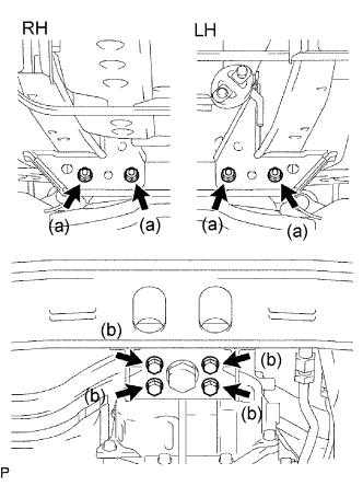
Install the stiffener plate RH with the 4 bolts.
Torque:
72 N*m{
730 kgf*cm
, 53 ft.*lbf
}
Install the stiffener plate LH with the 4 bolts.
Torque:
72 N*m{
730 kgf*cm
, 53 ft.*lbf
}
3.
INSTALL EXHAUST MANIFOLD STAY (for 1TR-FE)
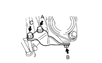
Install the exhaust manifold stay with the 3 bolts.
Torque:
44 N*m{
449 kgf*cm
, 32 ft.*lbf
}
for bolt A
30 N*m{
306 kgf*cm
, 22 ft.*lbf
}
for bolt B
72 N*m{
730 kgf*cm
, 53 ft.*lbf
}
for bolt C
4.
INSTALL REAR NO. 1 ENGINE MOUNTING INSULATOR
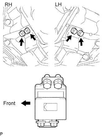
Install the mounting insulator with the 4 bolts.
Torque:
44 N*m{
449 kgf*cm
, 32 ft.*lbf
}
5.
INSTALL NO. 3 FRAME CROSSMEMBER SUB-ASSEMBLY
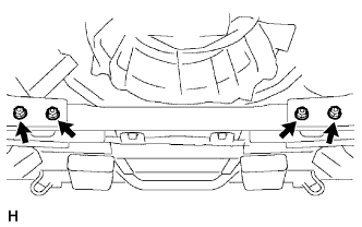
Install the frame crossmember with the 4 bolts and 4 nuts.
Torque:
50 N*m{
510 kgf*cm
, 37 ft.*lbf
}
Install the 4 set bolts to the No. 1 engine mounting insulator rear.
Torque:
17 N*m{
173 kgf*cm
, 13 ft.*lbf
}
6.
INSTALL STARTER ASSEMBLY
for 2KD-FTV for 2.0kW Type: (Click here) for 2KD-FTV for 2.2 kW Type: (Click here) for 1TR-FE for 1.0kW Type: (Click here) for 1TR-FE for 1.7kW Type: (Click here)
7.
CONNECT CLUTCH RELEASE CYLINDER ASSEMBLY
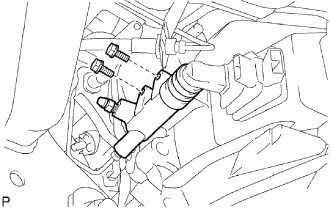
Install the clutch release cylinder with the 2 bolts.
Torque:
12 N*m{
120 kgf*cm
, 9 ft.*lbf
}
8.
CONNECT WIRE HARNESS
Connect the back-up light switch connector and speedometer sensor connector.
Install the frame crossmember with the 4 bolts and 4 nuts.
Torque:
50 N*m{
510 kgf*cm
, 37 ft.*lbf
}
12.
ADD MANUAL TRANSMISSION OIL
Stop the vehicle on a level surface.
Remove the filler plug and gasket.
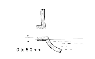
Check that the oil level is between 0 to 5 mm (0 to 0.20 in.) from the bottom lip of the filler plug opening. If the result is not as specified, add transmission oil.
Oil grade:
GL-4
Viscosity:
SAE 75W-90, 80w or 80W-90
Capacity:
2.2 liters (2.3 US qts, 1.9 Imp. qts)
NOTICE:
Too much or too little oil will lead to transmission problems.
After adjusting the oil level, drive the vehicle and check the oil level again.
Check for oil leakage when the oil level is low. If leakage is found, repair the area necessary to stop the leak. Replace damaged parts as necessary.
Install a new gasket and the filler plug.
Torque:
37 N*m (377 kgf*cm, 27 ft.*lbf)
13.
INSTALL NO. 1 ENGINE UNDER COVER
Torque:
28 N*m{
286 kgf*cm
, 21 ft.*lbf
}
14.
INSTALL ENGINE UNDER COVER
Torque:
28 N*m{
286 kgf*cm
, 21 ft.*lbf
}
15.
INSTALL FLOOR SHIFT SHIFT LEVER ASSEMBLY
Cover the shift lever cap with a cloth.
Press down on the shift lever cap and rotate it clockwise to install it.
HINT:
Apply MP grease to the tip of the shift lever.
16.
INSTALL SHIFT LEVER BOOT ASSEMBLY
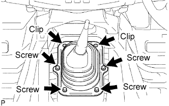
Install the shift lever boot with the 4 screws and 2 clips.