1KD-FTV INTAKE / EXHAUST EXHAUST MANIFOLD W/ TURBOCHARGER(w/ DPF) INSTALLATION
PROCEDURE

 1.INSTALL COMPRESSOR INLET ELBOW
Install a new gasket and the compressor inlet elbow to the turbocharger sub-assembly with the 2 nuts.
- Torque:
- 19 N*m (194 kgf*cm, 14 ft.*lbf)
Install the No. 7 water by-pass hose and No. 9 water by-pass hose to the compressor inlet elbow.
2.INSTALL NO. 1 TURBO WATER PIPE SUB-ASSEMBLY
Install a new gasket and the No. 1 turbo water pipe to the turbocharger sub-assembly with the 2 nuts and bolt.
- Torque:
- for bolt : 8.0 N*m (82 kgf*cm, 71 in.*lbf)
- for nut : 12 N*m (122 kgf*cm, 9 ft.*lbf)
Connect the No. 2 water by-pass hose to the compressor inlet elbow.
3.INSTALL TURBOCHARGER SUB-ASSEMBLY
Temporarily install a new gasket with the turbocharger and 3 new nuts.
- HINT:
-
It is easier to install the turbo oil inlet pipe if the 3 nuts are only loosely installed.
Temporarily install the turbo oil inlet pipe.
- HINT:
-
Before installing the turbo oil inlet pipe, clean it.
Install a new gasket and the turbo oil inlet pipe with the 2 nuts, but only loosely install the nuts.
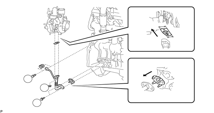
| *1 | New Gasket | *2 | Claw |
| *3 | Narrow | *4 | Wide |

|
Outside | - | - |
- NOTICE:
-
The notch (narrow part) of the gasket must face the engine.
Install a new gasket and the turbo oil inlet pipe with the 2 bolts, but only loosely install the bolts.
- NOTICE:
-
The claws of the gasket must face the pipe.
Install a new gasket and the turbo oil inlet pipe with the union bolt, but only loosely install the union bolt.
Temporarily install the turbocharger stay with the 2 bolts and a new nut.
Tighten the 3 nuts of the turbocharger.
- Torque:
- 52 N*m (530 kgf*cm, 38 ft.*lbf)
Tighten the union bolt labeled B.
- Torque:
- 36 N*m (367 kgf*cm, 27 ft.*lbf)
Tighten the 2 nuts labeled A.
- Torque:
- 13 N*m (133 kgf*cm, 10 ft.*lbf)
Tighten the 2 bolts labeled C.
- Torque:
- 12 N*m (122 kgf*cm, 9 ft.*lbf)
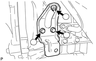
Tighten the 2 bolts and nut of the turbocharger stay in the order shown in the illustration.
- Torque:
- 38 N*m (387 kgf*cm, 28 ft.*lbf)
Attach the wire harness clamp and connect the 2 connectors.
4.CONNECT NO. 1 TURBO WATER HOSE
Connect the No. 1 turbo water hose and No. 9 water by-pass hose.
5.INSTALL TURBINE OUTLET ELBOW
Install a new gasket and the No. 4 water by-pass pipe to the turbine outlet elbow with the union bolt.
- Torque:
- 35 N*m (357 kgf*cm, 26 ft.*lbf)
Install a new gasket and the No. 3 water by-pass pipe to the turbine outlet elbow with the bolt and union bolt.
- Torque:
- for bolt : 21 N*m (214 kgf*cm, 15 ft.*lbf)
- for union bolt : 35 N*m (357 kgf*cm, 26 ft.*lbf)
Temporarily install the turbine outlet elbow and a new gasket with 3 new nuts.
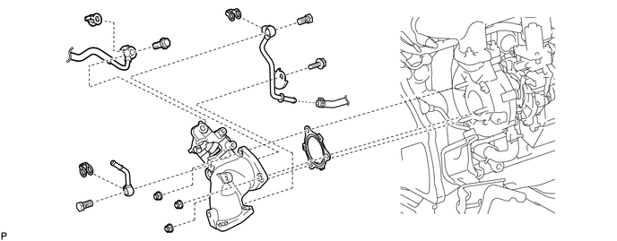
| *1 | New Gasket | *2 | Union Bolt |
| *3 | No. 3 Water By-pass Pipe | *4 | No. 4 Water By-pass Pipe |
| *5 | No. 3 Turbo Water Hose | *6 | Turbine Outlet Elbow |
| *7 | No. 1 Fuel Pipe | - | - |
Temporarily install the No. 1 fuel pipe and a new gasket with the union bolt.
Tighten the 3 nuts of the turbine outlet elbow.
- Torque:
- 26 N*m (260 kgf*cm, 19 ft.*lbf)
Connect the No. 3 water by-pass pipe to the No. 3 turbo water hose.
6.TIGHTEN NO. 1 FUEL PIPE
Tighten the union bolt of the No. 1 fuel pipe.
- Torque:
- 28 N*m (286 kgf*cm, 21 ft.*lbf)
Attach the clamp and connect the No. 4 turbo water hose to the No. 4 water by-pass pipe.
Connect the exhaust fuel addition injector connector.
7.INSTALL NO. 2 TURBINE OUTLET ELBOW
Install a new gasket and the No. 2 turbine outlet elbow with 3 new nuts.
- Torque:
- 30 N*m (306 kgf*cm, 22 ft.*lbf)
8.INSTALL TURBINE OUTLET ELBOW STAY
Install the turbine outlet elbow stay with the bolt and nut.
- Torque:
- 60 N*m (612 kgf*cm, 44 ft.*lbf)
Attach the wire harness clamp.
9.INSTALL NO. 3 EXHAUST MANIFOLD HEAT INSULATOR
Install the No. 3 exhaust manifold heat insulator with the 2 bolts.
- Torque:
- 12 N*m (122 kgf*cm, 9 ft.*lbf)
10.INSTALL NO. 2 EXHAUST MANIFOLD HEAT INSULATOR
Install the No. 2 exhaust manifold heat insulator with the 2 bolts.
- Torque:
- 13 N*m (133 kgf*cm, 10 ft.*lbf)
11.TEMPORARILY INSTALL NO. 1 EXHAUST MANIFOLD HEAT INSULATOR
Temporarily install the No. 1 exhaust manifold heat insulator with the bolt.
12.INSTALL NO. 1 TURBO INSULATOR
Temporarily install the No. 1 turbo insulator with the 2 bolts.
Tighten the 2 bolts of the No. 1 exhaust manifold heat insulator and the bolt of the No. 1 turbo insulator.
- Torque:
- 12 N*m (122 kgf*cm, 9 ft.*lbf)
13.INSTALL VENTILATION PIPE
Connect the 2 ventilation hoses to the cylinder head cover and compressor inlet elbow.
Install the ventilation pipe to the cylinder head with the bolt.
- Torque:
- 20 N*m (204 kgf*cm, 15 ft.*lbf)
14.INSTALL AIR CLEANER ASSEMBLY
Install the air cleaner together with the No. 1 air cleaner hose with the 2 bolts.
- Torque:
- 14 N*m (143 kgf*cm, 10 ft.*lbf)
Connect the No. 1 air cleaner hose and tighten the hose clamp of the compressor inlet elbow.
Connect the mass air flow meter connector and attach the wire harness clamp.
15.INSTALL FRONT FENDER SEAL
Install the front fender seal with the 5 clips.
16.INSTALL FRONT FENDER APRON SEAL UPPER
Install the front fender apron seal upper with the 5 clips.
17.INSTALL INTERCOOLER ASSEMBLY
18.INSTALL FRONT EXHAUST PIPE ASSEMBLY
19.CONNECT CABLE TO NEGATIVE BATTERY TERMINAL
- NOTICE:
-
When disconnecting the cable, some systems need to be initialized after the cable is reconnected (See page General>INTRODUCTION>REPAIR INSTRUCTION>INITIALIZATION).
20.ADD ENGINE COOLANT
21.BLEED AIR FROM FUEL SYSTEM
22.INSPECT FOR COOLANT LEAK
23.INSPECT FOR OIL LEAK
24.INSPECT FOR FUEL LEAK
25.INSPECT FOR EXHAUST GAS LEAK
26.INSTALL NO. 2 ENGINE UNDER COVER
27.INSTALL NO. 1 ENGINE UNDER COVER
28.INSTALL FRONT WHEEL RH