2TR-FE INTAKE / EXHAUST INTAKE MANIFOLD INSTALLATION
PROCEDURE

 1.INSTALL STUD BOLT
- NOTICE:
-
If a stud bolt is deformed or its threads are damaged, replace it.
Using an E6 "TORX" socket wrench, install the 2 stud bolts to the intake manifold.
- Torque:
- 3.0 N*m (31 kgf*cm, 27 in.*lbf)
2.INSTALL INTAKE MANIFOLD
Install the purge line hose to the intake manifold.
Install the 2 wire harness clamp brackets to the intake manifold with the 2 bolts.
- Torque:
- 8.0 N*m (82 kgf*cm, 71 in.*lbf)
Install a new gasket to the intake manifold.
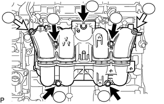

|
Bolt |

|
Nut |
Install the intake manifold with the 5 bolts and 2 nuts, and tighten the bolts and nuts in the sequence shown in the illustration.
- Torque:
- 25 N*m (255 kgf*cm, 18 ft.*lbf)
Connect the No. 3 PCV hose and vacuum hose to the intake manifold.
Attach the No. 2 water by-pass hose.
Attach the No. 1 fuel hose to the intake manifold.
Attach the 3 wire harness clamps to the 2 wire harness clamp brackets.
3.INSTALL PURGE VSV
4.INSTALL FRONT UPPER FENDER APRON SEAL
Install the front upper fender apron seal with the 5 clips.
5.INSTALL THROTTLE BODY WITH MOTOR ASSEMBLY
6.INSTALL STARTER ASSEMBLY
for 1.6 kW Type: (See page Engine / Hybrid System>2TR-FE STARTING>STARTER(for 1.6 kW Type)>INSTALLATION)
for 1.7 kW Type: (See page Engine / Hybrid System>2TR-FE STARTING>STARTER(for 1.7 kW Type)>INSTALLATION)
7.CONNECT CABLE TO NEGATIVE BATTERY TERMINAL
- NOTICE:
-
When disconnecting the cable, some systems need to be initialized after the cable is reconnected (See page General>INTRODUCTION>REPAIR INSTRUCTION>INITIALIZATION).