1GR-FE COOLING WATER PUMP INSTALLATION
PROCEDURE

 1.INSTALL ENGINE WATER PUMP ASSEMBLY
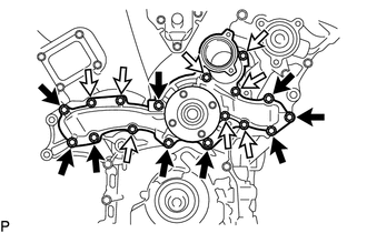

|
Bolt A |

|
Bolt B |
Install a new gasket and the engine water pump assembly with the 17 bolts.
- Torque:
- for bolt A : 21 N*m (214 kgf*cm, 15 ft.*lbf)
- for bolt B : 11 N*m (112 kgf*cm, 8 ft.*lbf)
2.INSTALL V-RIBBED BELT TENSIONER ASSEMBLY
3.INSTALL GENERATOR ASSEMBLY
4.INSTALL NO. 2 IDLER PULLEY
w/ Idler Pulley Cover Plate:
Install the 2 idler pulley cover plates, 2 No. 2 idler pulleys and 2 No. 2 idler pulley cover plates with the 2 bolts.
- Torque:
- 54 N*m (551 kgf*cm, 40 ft.*lbf)
w/o Idler Pulley Cover Plate:
Install the 2 No. 2 idler pulleys and 2 No. 2 idler pulley cover plates with the 2 bolts.
- Torque:
- 54 N*m (551 kgf*cm, 40 ft.*lbf)
for Integrated Type:
Install the 2 No. 2 idler pulleys with the 2 bolts.
- Torque:
- 54 N*m (551 kgf*cm, 40 ft.*lbf)
5.INSTALL WATER INLET ASSEMBLY
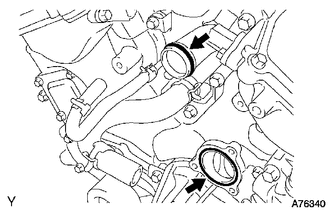
Install a new O-ring to the water outlet pipe.
Install a new gasket to the water pump.
Apply soapy water to the O-ring.
Install the water inlet assembly to the 5 bolts.
- Torque:
- 9.0 N*m (92 kgf*cm, 80 in.*lbf)
Connect the 5 water by-pass hoses.
Install the 2 radiator hoses to the water inlet assembly.
6.CONNECT NO. 2 PCV HOSE
7.INSTALL FAN SHROUD
8.CONNECT RADIATOR HOSE INLET
Connect the radiator hose inlet to the radiator.
9.CONNECT RADIATOR HOSE OUTLET
Connect the radiator hose outlet to the radiator.
10.CONNECT CABLE TO NEGATIVE BATTERY TERMINAL
- NOTICE:
-
When disconnecting the cable, some systems need to be initialized after the cable is reconnected (See page General>INTRODUCTION>REPAIR INSTRUCTION>INITIALIZATION).
11.ADD ENGINE COOLANT
12.INSPECT FOR COOLANT LEAK
13.INSTALL AIR CLEANER ASSEMBLY
14.INSTALL V-BANK COVER
15.INSTALL NO. 1 ENGINE UNDER COVER
16.INSTALL ENGINE SIDE COVER SUB-ASSEMBLY RH
17.INSTALL ENGINE SIDE COVER SUB-ASSEMBLY LH