| NG |  |
| REPAIR FUEL LEAK POINT |
DTC P0093 Fuel System Leak Detected - Large Leak |
DTC P029D Cylinder 1 - Injector Leaking |
DTC P02A1 Cylinder 2 - Injector Leaking |
DTC P02A5 Cylinder 3 - Injector Leaking |
DTC P02A9 Cylinder 4 - Injector Leaking |
| DTC Detection Drive Pattern | DTC Detection Condition | Trouble Area |
| After idling for 60 seconds, run engine at 2500 rpm for 30 seconds. Fully depress the accelerator pedal for 5 seconds, and then release it. (*A) Rev the engine to 3000 rpm and fully release the accelerator pedal immediately after the engine reaches 3000 rpm. (*B) Repeat procedures (*A) and (*B) 5 times. | DTC P0093 Fuel pressure drop before and after fuel injection is larger than the threshold a certain number of times (0.2 seconds or more). (1 trip detection logic) |
|
| DTC P029D, P02A1, P02A5, P02A9 When the engine speed is at 650 rpm or more, the fuel pressure drop (slope of the line) is larger than the threshold and there is a time difference in the pressure drop of this cylinder compared to other cylinders for 1 second or more. (1 trip detection logic) |
| DTC No. | Data List |
| P0093 P029D P02A1 P02A5 P02A9 |
|
| Engine Speed | Fuel Press |
| Idling | Approximately 30000 to 50000 kPa |
| 3000 rpm (No engine load) | Approximately 60000 to 95000 kPa |
| Required sensors | Fuel pressure sensor |
| Frequency of operation | Continuous |
| Duration | 1 second |
| MIL operation | 1 driving cycle |
| 1.CHECK FOR FUEL LEAKS (IN HIGH-PRESSURE AREAS) |
Before starting the engine, visually check for fuel leaks from the fuel supply pump assembly, injector assembly, common rail assembly, and the fuel pipes in high-pressure areas.
|
| ||||
| OK | |
 |
| 2.CHECK FOR ANY OTHER DTCS OUTPUT AND RECORD STORED DTC AND FREEZE FRAME DATA (PROCEDURE 2) |
Connect the GTS to the DLC3.
Turn the ignition switch to ON and turn the GTS on.
Enter the following menus: Powertrain / Engine / Trouble Codes.
Read the DTCs and freeze frame data.
| Result | Proceed to |
| P0093 and P13A1, P13A2, P13A3, P13A6, P13A7, P13A8, P13AB, P13AC, P13AD, P13B1, P13B2, P13B3, P13C3, P13C8, P13CD and/or P13D3 are output | C |
| P0093 and P0335, P0339 and/or P0340 are output | B |
| Except above | A |
|
| ||||
|
| ||||
| A | |
|
| 3.CHECK FUEL RECEIVER GAUGE (AMOUNT OF FUEL) |
Check if the fuel level is low.
| Result | Proceed to |
| The indicator (fuel warning light) is illuminated | A |
| The indicator (fuel warning light) is not illuminated | B |
|
| ||||
| A | |
|
| 4.ADD FUEL |
Add fuel.
| NEXT | |
|
| 5.CHECK WHETHER DTC OUTPUT RECURS |
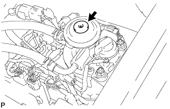 |
Using the hand pump mounted on the fuel filter cap, bleed the air from the fuel system. Continue pumping until the pump resistance increases.
Start the engine.
When the engine can be started, proceed to the next step.
If the engine cannot be started, bleed the air again using the hand pump until the hand pump resistance increases. Then start the engine.
Turn the ignition switch off.
Connect the GTS to the DLC3.
Turn the ignition switch to ON and turn the GTS on.
Clear the DTCs (Click here).
Start the engine. (*A)
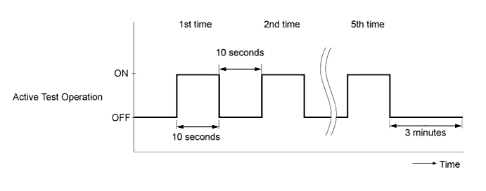
Enter the following menus: Powertrain / Engine / Active Test / Test the Fuel Leak. (*B)
Perform the following test 5 times with on/off intervals of 10 seconds: Active Test / Test the Fuel Leak. (*C)
Allow the engine to idle for 3 minutes or more after performing the Active Test for the fifth time. (*D)
Enter the following menus: Powertrain / Engine / Trouble Codes.
Read Current DTCs.
When no DTCs are output, the air bleeding is completed.
If any DTCs are output, proceed to the next step.
Repeat steps (*A) to (*D).
Clear the DTCs (Click here).
Start the engine and warm it up.
Confirm that the shift lever is in neutral and securely apply the parking brake.
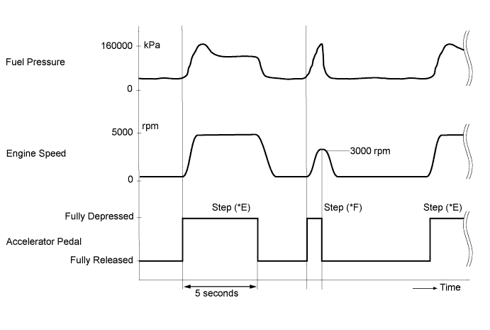
Fully depress the accelerator pedal for 5 seconds, and then release it. (*E)
Rev the engine to 3000 rpm and fully release the accelerator pedal immediately after the engine reaches 3000 rpm. (*F)
Repeat procedures (*E) and (*F) 5 times.
Enter the following menus: Powertrain / Engine / Trouble Codes.
Read Current DTCs.
| Result | Proceed to |
| DTC is output | A |
| No DTC is output | B |
|
| ||||
| A | |
|
| 6.CHECK FREEZE FRAME DATA (INJECTION FEEDBACK VAL #1 TO #4) |
Read the value of Injection Feedback Val #1 to #4 in the freeze frame data recorded in Procedure 2.
| Result | Proceed to |
| Injection Feedback Val for at least one cylinder is 5 mm3/st in at least 1 set of freeze frame data | B |
| Except above | A |
|
| ||||
| A | |
|
| 7.READ VALUE USING GTS (FUEL PRESS) |
Connect the GTS to the DLC3.
Turn the ignition switch to ON and turn the GTS on.
Clear the DTCs (Click here).
Enter the following menus: Powertrain / Engine / Data List / Fuel Press.
Start the engine.
Read the value of Fuel Press while cranking and idling the engine.
| Result | Proceed to |
| The engine cannot be started or the engine can be started but Fuel Press is below 20000 kPa 2 seconds after the starter signal changes from OFF to ON | B |
| Except above | A |
|
| ||||
| A | |
|
| 8.READ VALUE USING GTS (INJECTION FEEDBACK VAL #1 TO #4) |
Connect the GTS to the DLC3.
Turn the ignition switch to ON and turn the GTS on.
Start the engine and warm it up.
Enter the following menus: Powertrain / Engine / Data List / Injection Feedback Val #1 to #4.
Read the values.
| Tester Display | Engine Condition* | Normal Value |
| Injection Feedback Val #1 Injection Feedback Val #2 Injection Feedback Val #3 Injection Feedback Val #4 | Idling | -3.0 mm3/st to 3.0 mm3/st |
| Result | Proceed to |
| Injection Feedback Val for at least one cylinder is more than 3 mm3/st and engine vibration is abnormally large | B |
| Except above | A |
|
| ||||
| A | |
|
| 9.CHECK ENGINE SPEED |
Start the engine and drive the vehicle until the engine coolant temperature reaches 60°C (140°F) or higher.
Stop the vehicle and allow the engine to idle.
While checking the tachometer, fully depress the accelerator pedal for 5 seconds, and then release it.*1
Repeat procedure *1 5 times.
| Result | Proceed to |
| No problems such as sluggishness or variations in the tachometer reading | A |
| Except above | B |
|
| ||||
| A | |
|
| 10.CHECK FREEZE FRAME DATA |
Read the value of Injector Leaking Count #1 to #4, and i-ART Learning Status History #1 to #4 in the freeze frame data recorded in Procedure 2.
| NEXT | |
|
| 11.CLEAN FUEL FILTER CASE AND REPLACE FUEL FILTER |
Clean the fuel filter case and replace the fuel filter.
| NEXT | |
|
| 12.BLEED AIR FROM FUEL SYSTEM |
Bleed the air from the fuel system .
| NEXT | |
|
| 13.PERFORM ACTIVE TEST USING GTS (TEST THE FUEL LEAK) |
Connect the GTS to the DLC3.
Turn the ignition switch to ON and turn the GTS on.
Start the engine.
Enter the following menus: Powertrain / Engine / Active Test / Test the Fuel Leak / Data List / Fuel Press, Target Common Rail Pressure, and Target Pump SCV Current.
Take a snapshot with the GTS during the Active Test.
Measure the difference between the target fuel pressure (Target Common Rail Pressure) and the actual fuel pressure (Fuel Press) when the "Test the Fuel Leak" Active Test is performed (Click here).
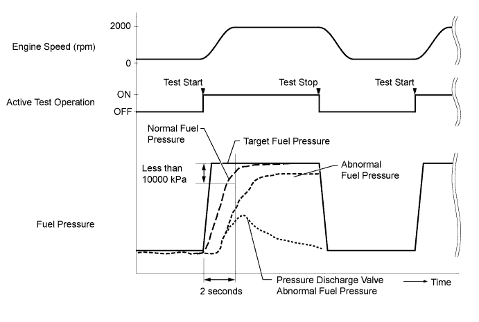
| Result | Proceed to |
| The difference between the target fuel pressure and the actual fuel pressure 2 seconds after the Active Test starts is less than 10000 kPa | A |
| Except above | B |
|
| ||||
| A | |
|
| 14.PERFORM ACTIVE TEST USING GTS (CONTROL THE SELECT CYLINDER FUEL CUT) |
Connect the GTS to the DLC3.
Start the engine and turn the GTS on.
Enter the following menus: Powertrain / Engine / Active Test / Control the Select Cylinder Fuel Cut.
|
| ||||
| 15.INSPECT INJECTOR ASSEMBLY (INSPECTION FOR VALVE CLOSING PROBLEM) |
Remove the glow plug for all the cylinders (Click here).
Visually check if there is fuel on the glow plugs.
Install the glow plug (Click here).
| NEXT | |
|
| 16.REPLACE INJECTOR ASSEMBLY OF MALFUNCTIONING CYLINDER |
Replace the injector assembly of the malfunctioning cylinder (Click here).
| NEXT | |
|
| 17.BLEED AIR FROM FUEL SYSTEM |
Bleed the air from the fuel system .
|
| ||||
| 18.READ VALUE USING GTS (ENGINE SPEED) |
Connect the GTS to the DLC3.
Turn the ignition switch to ON and turn the GTS on.
Enter the following menus: Powertrain / Engine / Data List / Engine Speed.
Read the value while cranking and idling the engine.
| Tester Display | Engine Condition | Specified Condition |
| Engine Speed | Cranking | 50 to 400 rpm |
| Idling with warm engine | 700 to 800 rpm |
|
| ||||
| OK | |
|
| 19.INSPECT ECM (FUEL PRESSURE SENSOR OUTPUT VOLTAGE) |
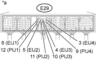 |
Connect the positive (+) probe of an oscilloscope to the PIJ terminal of the ECM connector and the negative (-) probe to the EIJ terminal of the ECM.
| *a | Component with harness connected (ECM) |
Turn the ignition switch to ON.
Check for any noise in the waveform when vibration is applied to the wire harness and connectors between the injector assembly and ECM.
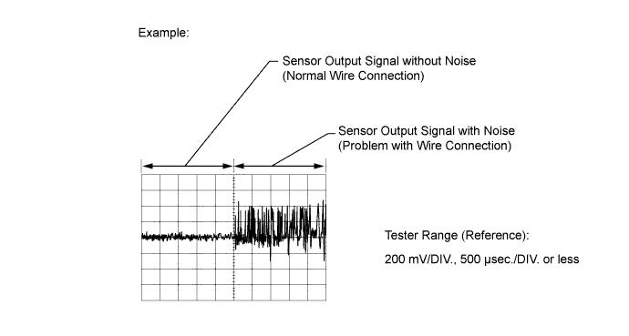
| Tester Connection | Condition | Specified Condition |
| E29-12 (PIJ1) - E29-6 (EIJ1) | Vibration is applied to the wire harness and connectors | No noise in the waveform |
| E29-11 (PIJ2) - E29-5 (EIJ2) | ||
| E29-10 (PIJ3) - E29-4 (EIJ3) | ||
| E29-9 (PIJ4) - E29-3 (EIJ4) |
| Result | Proceed to |
| MIL comes on or noise present in the waveform | B |
| Except above | A |
|
| ||||
| A | |
|
| 20.CHECK FOR INTERMITTENT PROBLEMS |
Check for intermittent problems (Click here).
|
| ||||
| 21.REPLACE CRANKSHAFT POSITION SENSOR |
Replace the crankshaft position sensor (Click here).
|
| ||||
| 22.REPAIR OR REPLACE HARNESS OR CONNECTOR (ECM - FUEL PRESSURE SENSOR) |
Repair or replace the harness or connector.
| NEXT | |
|
| 23.INSPECT ECM (FUEL PRESSURE SENSOR OUTPUT VOLTAGE) |
|
Connect the positive (+) probe of an oscilloscope to the PIJ terminal of the ECM connector and the negative (-) probe to the EIJ terminal of the ECM.
| *a | Component with harness connected (ECM) |
Turn the ignition switch to ON.
Check for any noise in the waveform when vibration is applied to the wire harness and connectors between the injector assembly and ECM.
| Tester Connection | Condition | Specified Condition |
| E29-12 (PIJ1) - E29-6 (EIJ1) | Vibration is applied to the wire harness and connectors | No noise in the waveform |
| E29-11 (PIJ2) - E29-5 (EIJ2) | ||
| E29-10 (PIJ3) - E29-4 (EIJ3) | ||
| E29-9 (PIJ4) - E29-3 (EIJ4) |
| Result | Proceed to |
| MIL comes on or noise present in the waveform | A |
| Except above | B |
|
| ||||
| A | |
|
| 24.REPLACE INJECTOR ASSEMBLY (FUEL PRESSURE SENSOR) |
Replace the injector assembly (Click here).
| NEXT | |
|
| 25.BLEED AIR FROM FUEL SYSTEM |
Bleed the air from the fuel system .
|
| ||||
| 26.CHECK WHETHER DTC OUTPUT RECURS |
Connect the GTS to the DLC3.
Turn the ignition switch to ON and turn the GTS on.
Enter the following menus: Powertrain / Engine / Trouble Codes.
Clear the DTCs (Click here).
Start the engine.
Warm up the engine (engine coolant temperature is 70°C (158°F) or higher).
Confirm that the shift lever is in neutral and securely apply the parking brake.
Fully depress the accelerator pedal for 5 seconds, and then release it. (*A)
Rev the engine to 3000 rpm and fully release the accelerator pedal immediately after the engine reaches 3000 rpm. (*B)
Repeat procedures (*A) and (*B) 5 times.
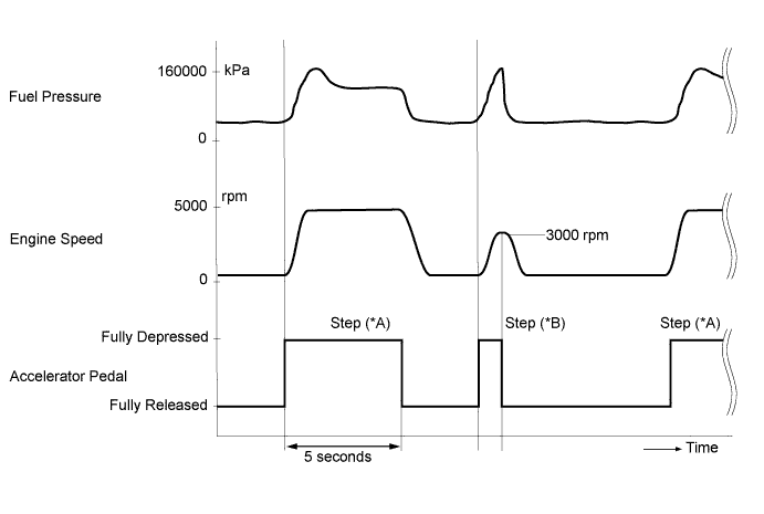
Enter the following menus: Powertrain / Engine / Trouble Codes.
Read the DTCs.
| NEXT | ||
 | ||
| ||
