2TR-FE LUBRICATION OIL PUMP REMOVAL
CAUTION / NOTICE / HINT
The necessary procedures (adjustment, calibration, initialization, or registration) that must be performed after parts are removed, installed, or replaced during the throttle body with motor assembly removal/installation are shown below.
| Replacement Part or Procedure | Necessary Procedures | Effects/Inoperative when not Performed | Link |
|---|---|---|---|
| Replacement of throttle body with motor assembly | Inspection After Repair | Poor idle, engine start, etc. | ( ) |
| Cleaning the deposits from the throttle body with motor assembly |
PROCEDURE

 1.REMOVE ENGINE ASSEMBLY
2.INSTALL ENGINE TO ENGINE STAND
19500
3.REMOVE IGNITION COIL ASSEMBLY
19100P
4.REMOVE SPARK PLUG
12229
5.REMOVE PCV PIPE
22030
6.REMOVE THROTTLE BODY WITH MOTOR ASSEMBLY
23814B
7.REMOVE FUEL DELIVERY PIPE
23250
8.REMOVE FUEL INJECTOR ASSEMBLY
17111
9.REMOVE INTAKE MANIFOLD
27020
10.REMOVE GENERATOR ASSEMBLY
88431
11.REMOVE NO. 1 COMPRESSOR MOUNTING BRACKET
16620D
12.REMOVE V-RIBBED BELT TENSIONER ASSEMBLY
16321
13.REMOVE WATER INLET
16331A
14.REMOVE THERMOSTAT
16603
15.REMOVE NO. 1 IDLER PULLEY SUB-ASSEMBLY
16268
16.REMOVE NO. 1 WATER BY-PASS PIPE
12108
17.REMOVE OIL FILLER CAP SUB-ASSEMBLY
11301M
18.REMOVE CAMSHAFT POSITION SENSOR (for Intake Side)
11301M
19.REMOVE CAMSHAFT POSITION SENSOR (for Exhaust Side)
11101J
20.REMOVE CAMSHAFT TIMING OIL CONTROL VALVE ASSEMBLY (for Exhaust Side)
11201
21.REMOVE CYLINDER HEAD COVER SUB-ASSEMBLY
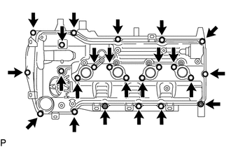
Remove the 21 bolts, 2 nuts, 2 plate washers, 2 seal washers and cylinder head cover sub-assembly.
Remove the cylinder head cover gasket from the cylinder head cover sub-assembly.
Remove the No. 1 camshaft bearing cap oil hole gasket from the cylinder head cover connector sub-assembly.
13471
22.REMOVE CRANKSHAFT PULLEY
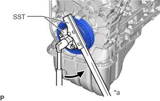
| *a | Hold |

|
Turn |
Using SST, hold the crankshaft pulley and loosen the crankshaft pulley set bolt until 2 or 3 threads are screwed into the crankshaft.
- SST
- 09213-54015 (91651-60855)
09330-00021
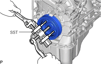
Using SST and the crankshaft pulley set bolt, remove the crankshaft pulley.
- SST
- 09950-50013 (09951-05010, 09952-05010, 09953-05010, 09954-05021)
- HINT:
-
Apply lubricant to the threads and end of SST.
12144
23.REMOVE OIL PAN COVER SILENCER
Remove the 4 No. 1 oil pan plugs and oil pan cover silencer.
12102A
24.REMOVE NO. 2 OIL PAN SUB-ASSEMBLY
Remove the oil pan drain plug and gasket.
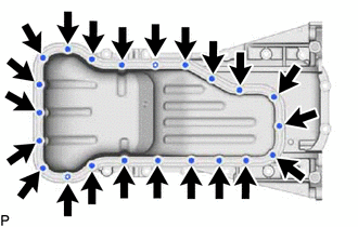
Remove the 16 bolts, 4 adjusting screws and 2 nuts.
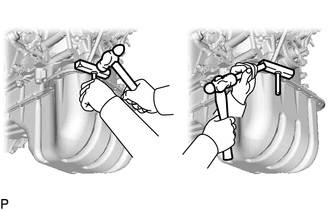
Insert the blade of an oil pan seal cutter between the oil pan sub-assembly and No. 2 oil pan sub-assembly. Cut through the applied sealer and remove the No. 2 oil pan sub-assembly.
- NOTICE:
-
Be careful not to damage the contact surfaces of the oil pan sub-assembly and No. 2 oil pan sub-assembly.
15104
25.REMOVE OIL STRAINER SUB-ASSEMBLY
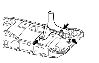
Remove the 2 bolts, nut, oil strainer sub-assembly and gasket.
12101
26.REMOVE OIL PAN SUB-ASSEMBLY
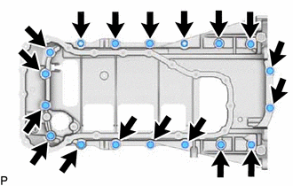
Remove the 16 bolts and 2 nuts.
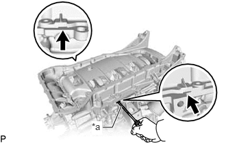
| *a | Protective Tape |
Remove the oil pan sub-assembly by prying between the oil pan sub-assembly and cylinder block sub-assembly with a screwdriver.
- NOTICE:
-
Be careful not to damage the contact surfaces of the cylinder block sub-assembly and oil pan sub-assembly.
- HINT:
-
Tape the screwdriver tip before use.
11301K
27.REMOVE CRANKSHAFT POSITION SENSOR
11302
28.REMOVE TIMING CHAIN COVER SUB-ASSEMBLY
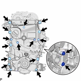
Remove the 16 bolts and nut shown in the illustration.
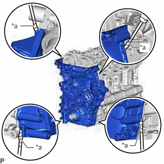
| *a | Protective Tape |
Remove the timing chain cover sub-assembly by prying between the timing chain cover sub-assembly and cylinder head sub-assembly or cylinder block sub-assembly with a screwdriver.
- NOTICE:
-
Be careful not to damage the contact surfaces of the cylinder head sub-assembly, cylinder block sub-assembly and timing chain cover sub-assembly.
- HINT:
-
Tape the screwdriver tip before use.
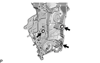
Remove the 3 O-rings.
16100
29.REMOVE ENGINE WATER PUMP ASSEMBLY
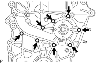
Remove the 8 bolts, engine water pump assembly and gasket.
11303A
30.REMOVE TIMING CHAIN CASE OIL SEAL
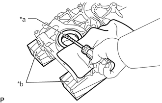
| *a | Protective Tape |
| *b | Wooden Block |
Place the timing chain cover sub-assembly on wooden blocks.
Using a screwdriver, pry out the timing chain case oil seal.
- HINT:
-
Tape the screwdriver tip before use.