RC60 / RC61 MANUAL TRANSMISSION / TRANSAXLE MANUAL TRANSMISSION ASSEMBLY INSTALLATION
PROCEDURE

 33146
1.INSTALL EXTENSION HOUSING DUST DEFLECTOR
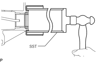
Using SST and hammer, tap in the extension housing dust deflector.
- SST
- 09513-36040
2.INSTALL WIRING HARNESS CLAMP BRACKET
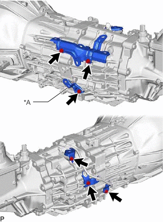
| *A | w/ Intelligent Manual Transmission Switch |
Install the 6 bolts and 5 wiring harness clamp brackets to the manual transmission assembly.
- Torque:
- 13 N*m (133 kgf*cm, 10 ft.*lbf)
33019C
3.INSTALL TRANSMISSION BREATHER SUB-ASSEMBLY
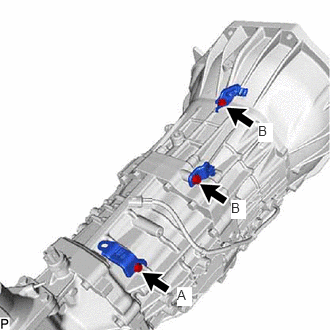
Install the 3 bolts and 3 brackets to the manual transmission assembly.
- Torque:
- for bolt A : 13 N*m (133 kgf*cm, 10 ft.*lbf)
- for bolt B : 19.0 N*m (194 kgf*cm, 14 ft.*lbf)
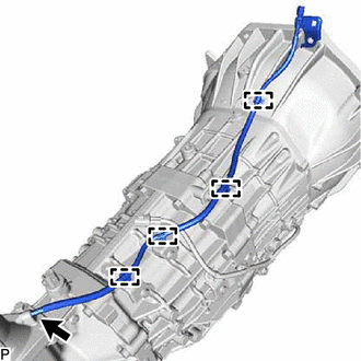
Install the transmission breather sub-assembly to the control shift lever retainer sub-assembly.
Attach the 4 breather hose clamps.
4.INSTALL MANUAL TRANSMISSION ASSEMBLY
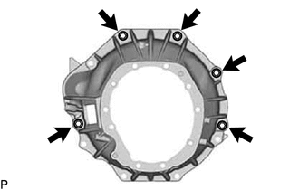
Install the manual transmission assembly with the 5 bolts.
- Torque:
- 71.5 N*m (729 kgf*cm, 53 ft.*lbf)
5.CONNECT WIRE HARNESS
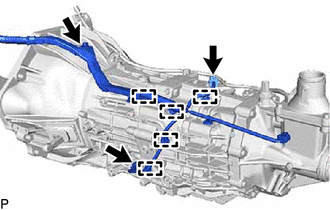
w/ Intelligent Manual Transmission Switch:
Connect the 2 connectors.
Install the bolt.
- Torque:
- 13 N*m (133 kgf*cm, 10 ft.*lbf)
Attach the 6 wire harness clamps.
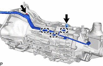
w/o Intelligent Manual Transmission Switch:
Connect the connector.
Install the bolt.
- Torque:
- 13 N*m (133 kgf*cm, 10 ft.*lbf)
Attach the 3 wire harness clamps.
12371A
6.INSTALL REAR ENGINE MOUNTING INSULATOR
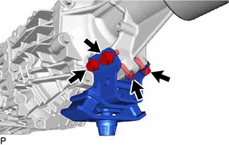
Install the rear engine mounting insulator to the manual transmission assembly with the 4 bolts.
- Torque:
- 47 N*m (479 kgf*cm, 35 ft.*lbf)
51204
7.INSTALL NO. 3 FRAME CROSSMEMBER SUB-ASSEMBLY
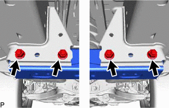
Install the No. 3 frame crossmember sub-assembly with the 4 nuts and 4 bolts.
- Torque:
- 57 N*m (581 kgf*cm, 42 ft.*lbf)
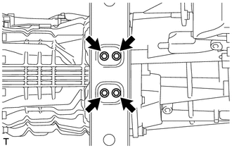
Install the 4 bolts to the No. 3 frame crossmember sub-assembly.
- Torque:
- 18.5 N*m (189 kgf*cm, 14 ft.*lbf)
8.CONNECT GROUND CABLE
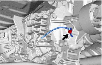
Connect the ground cable with the bolt.
- Torque:
- 19.5 N*m (199 kgf*cm, 14 ft.*lbf)
37100
9.INSTALL PROPELLER SHAFT WITH CENTER BEARING ASSEMBLY
for TMT Made:
Click hereDrivetrain>DRIVE SHAFT / PROPELLER SHAFT>PROPELLER SHAFT ASSEMBLY(for TMT Made)>INSTALLATION
for TSAM Made:
Click hereDrivetrain>DRIVE SHAFT / PROPELLER SHAFT>PROPELLER SHAFT ASSEMBLY(for TSAM Made)>INSTALLATION
33119
10.INSTALL STIFFENER PLATE LH
Install the stiffener plate LH with the 4 bolts.
- Torque:
- 71.5 N*m (729 kgf*cm, 53 ft.*lbf)
33118
11.INSTALL STIFFENER PLATE RH
Install the stiffener plate RH with the 4 bolts.
- Torque:
- 71.5 N*m (729 kgf*cm, 53 ft.*lbf)
12584
12.INSTALL NO. 4 CYLINDER BLOCK INSULATOR
Install the No. 4 cylinder block insulator.
28100
13.INSTALL STARTER ASSEMBLY (for 1GD-FTV)
for 2.0 kW Type:
Click hereEngine / Hybrid System>1GD-FTV STARTING>STARTER(for 2.0 kW Type)>INSTALLATION
for 2.2 kW Type
Click hereEngine / Hybrid System>1GD-FTV STARTING>STARTER(for 2.2 kW Type)>INSTALLATION
28100
14.INSTALL STARTER ASSEMBLY (for 2GD-FTV)
for 2.0 kW Type:
Click hereEngine / Hybrid System>2GD-FTV STARTING>STARTER(for 2.0 kW Type)>INSTALLATION
for 2.2 kW Type:
Click hereEngine / Hybrid System>2GD-FTV STARTING>STARTER(for 2.2 kW Type)>INSTALLATION
for 2.7 kW Type:
Click hereEngine / Hybrid System>2KD-FTV STARTING>STARTER(for 2.7 kW Type)>INSTALLATION
28100
15.INSTALL STARTER ASSEMBLY (for 2KD-FTV)
for 2.0 kW Type:
Click hereEngine / Hybrid System>2KD-FTV STARTING>STARTER(for 2.0 kW Type)>INSTALLATION
for 2.2 kW Type:
Click hereEngine / Hybrid System>2KD-FTV STARTING>STARTER(for 2.2 kW Type)>INSTALLATION
17410
16.INSTALL FRONT EXHAUST PIPE ASSEMBLY (for 1GD-FTV)
17410
17.INSTALL FRONT EXHAUST PIPE ASSEMBLY (for 2GD-FTV)
17410
18.INSTALL FRONT EXHAUST PIPE ASSEMBLY (for 2KD-FTV)
19.ADD MANUAL TRANSMISSION OIL
51442
20.INSTALL NO. 2 ENGINE UNDER COVER
51410
21.INSTALL NO. 1 ENGINE UNDER COVER ASSEMBLY
33548F
22.INSTALL NO. 1 FLOOR SHIFT BUSH
Install the No. 1 floor shift bush to the floor shift shift lever assembly.
33530F
23.INSTALL FLOOR SHIFT SHIFT LEVER ASSEMBLY
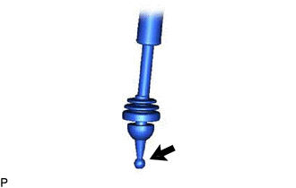

|
MP grease |
Apply MP grease to the tip of the floor shift shift lever assembly.
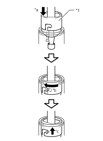
| *1 | Shift Lever Cap |
| *a | Press Down |
| *b | Clockwise |
| *c | Lock |
Cover the shift lever cap with a cloth.
While pressing down on the shift lever cap, turn it clockwise to install the floor shift shift lever assembly.
Attach the shift lever cap boot.
58280A
24.INSTALL SHIFT LEVER BOOT ASSEMBLY
Install the shift lever boot assembly with the 6 screws and 4 clips.
58810J
25.INSTALL CONSOLE BOX ASSEMBLY (w/ Console Box Lid)
58811A
26.INSTALL FRONT CONSOLE BOX (w/o Console Box Lid)
28800
27.CONNECT CABLE TO NEGATIVE BATTERY TERMINAL
- NOTICE:
-
When disconnecting the cable, some systems need to be initialized after the cable is reconnected.
-
Click hereGeneral>INTRODUCTION>REPAIR INSTRUCTION>INITIALIZATION