DOOR LOCK DOOR CONTROL RELAY ON-VEHICLE INSPECTION
CAUTION / NOTICE / HINT
- HINT:
- ·
Use the same procedure for RHD and LHD vehicles.
·The procedures listed below are for LHD vehicles.
PROCEDURE

 1. PRECAUTION
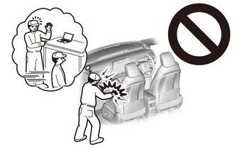
- CAUTION:
-
-
Be sure to read Precaution thoroughly before servicing.
-
for Type A:
-
Click hereVehicle Interior>SUPPLEMENTAL RESTRAINT SYSTEMS>AIRBAG SYSTEM(for Type A)>PRECAUTION
-
for Type B:
-
Click hereVehicle Interior>SUPPLEMENTAL RESTRAINT SYSTEMS>AIRBAG SYSTEM(for Type B)>PRECAUTION
- NOTICE:
-
After turning the ignition switch off, waiting time may be required before disconnecting the cable from the negative (-) battery terminal. Therefore, make sure to read the disconnecting the cable from the negative (-) battery terminal notice before proceeding with work.
-
Click hereGeneral>INTRODUCTION>REPAIR INSTRUCTION>PRECAUTION
2.DISCONNECT CABLE FROM NEGATIVE BATTERY TERMINAL
- CAUTION:
-
- ·
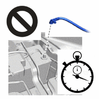
Wait at least 90 seconds after disconnecting the cable from the negative (-) battery terminal to disable the SRS system.
·If the airbag deploys for any reason, it may cause a serious accident.
- NOTICE:
-
When disconnecting the cable, some systems need to be initialized after the cable is reconnected.
-
Click hereGeneral>INTRODUCTION>REPAIR INSTRUCTION>INITIALIZATION
45100
3.REMOVE STEERING WHEEL ASSEMBLY
55410C
4.REMOVE INSTRUMENT CLUSTER FINISH PANEL ASSEMBLY
55905J
5.REMOVE CONTROL KNOB SUB-ASSEMBLY (for Manual Air Conditioning System)
55918A
6.REMOVE AIR INLET DAMPER CONTROL LEVER (for Manual Air Conditioning System)
84013A
7.REMOVE INTEGRATION PANEL SUB-ASSEMBLY (for Manual Air Conditioning System)
55900
8.REMOVE AIR CONDITIONING CONTROL ASSEMBLY (for Automatic Air Conditioning System)
84930G
9.REMOVE DOOR LOCK CONTROL RELAY
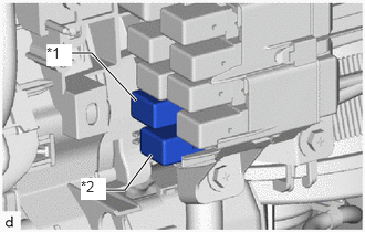
| *1 | No. 1 Door Lock Control Relay |
| *2 | No. 2 Door Lock Control Relay |
Remove the door lock control relay.
84930G
10.INSPECT NO. 1 DOOR LOCK CONTROL RELAY
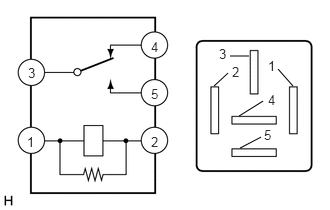
Inspect the No. 1 door lock control relay.
Measure the resistance according to the value(s) in the table below.
- Standard Resistance:
Tester Connection Condition Specified Condition 3 - 4 Battery voltage is not applied to terminals 1 and 2 Below 1 Ω Battery voltage is applied to terminals 1 and 2 10 kΩ or higher 3 - 5 Battery voltage is not applied to terminals 1 and 2 10 kΩ or higher Battery voltage is applied to terminals 1 and 2 Below 1 Ω
If the result is not as specified, replace the No. 1 door lock control relay.
84930H
11.INSPECT NO. 2 DOOR LOCK CONTROL RELAY
Inspect the No. 2 door lock control relay.
Measure the resistance according to the value(s) in the table below.
- Standard Resistance:
Tester Connection Condition Specified Condition 3 - 4 Battery voltage is not applied to terminals 1 and 2 Below 1 Ω Battery voltage is applied to terminals 1 and 2 10 kΩ or higher 3 - 5 Battery voltage is not applied to terminals 1 and 2 10 kΩ or higher Battery voltage is applied to terminals 1 and 2 Below 1 Ω
If the result is not as specified, replace the No. 2 door lock control relay.
84930G
12.INSTALL DOOR LOCK CONTROL RELAY
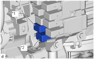
| *1 | No. 1 Door Lock Control Relay |
| *2 | No. 2 Door Lock Control Relay |
Install the door lock control relay.
84013A
13.INSTALL INTEGRATION PANEL SUB-ASSEMBLY (for Manual Air Conditioning System)
55918A
14.INSTALL AIR INLET DAMPER CONTROL LEVER (for Manual Air Conditioning System)
55905J
15.INSTALL CONTROL KNOB SUB-ASSEMBLY (for Manual Air Conditioning System)
55900
16.INSTALL AIR CONDITIONING CONTROL ASSEMBLY (for Automatic Air Conditioning System)
55410C
17.INSTALL INSTRUMENT CLUSTER FINISH PANEL ASSEMBLY
45100
18.INSTALL STEERING WHEEL ASSEMBLY
19.CONNECT CABLE TO NEGATIVE BATTERY TERMINAL
- NOTICE:
-
When disconnecting the cable, some systems need to be initialized after the cable is reconnected.
-
Click hereGeneral>INTRODUCTION>REPAIR INSTRUCTION>INITIALIZATION
20.CHECK SRS WARNING LIGHT
for Type A:
Click hereVehicle Interior>SUPPLEMENTAL RESTRAINT SYSTEMS>AIRBAG SYSTEM(for Type A)>DIAGNOSIS SYSTEM
for Type B:
Click hereVehicle Interior>SUPPLEMENTAL RESTRAINT SYSTEMS>AIRBAG SYSTEM(for Type B)>DIAGNOSIS SYSTEM