2KD-FTV ENGINE MECHANICAL CAMSHAFT INSTALLATION
CAUTION / NOTICE / HINT
- NOTICE:
- ·
When replacing the parts in the following chart (A), replace the No. 1 injection pipe sub-assembly, No. 2 injection pipe sub-assembly, No. 3 injection pipe sub-assembly, No. 4 injection pipe sub-assembly and/or fuel inlet pipe sub-assembly with new ones.
Replaced Parts (A) Pipes Requiring New Replacement ·Injector assembly (including shuffling the injector assemblies between the cylinders)
·Common rail assembly
·Cylinder head sub-assembly
·No. 1 injection pipe sub-assembly
·No. 2 injection pipe sub-assembly
·No. 3 injection pipe sub-assembly
·No. 4 injection pipe sub-assembly
·Supply pump assembly
·Common rail assembly
·Cylinder block sub-assembly
·Cylinder head sub-assembly
·Cylinder head gasket
·Timing Gear Case Assembly
Fuel inlet pipe sub-assembly
·After removing the No. 1 injection pipe sub-assembly, No. 2 injection pipe sub-assembly, No. 3 injection pipe sub-assembly, No. 4 injection pipe sub-assembly and fuel inlet pipe sub-assembly, clean them with a brush and compressed air.
PROCEDURE

 1.INSTALL CAMSHAFT SUB-ASSEMBLY
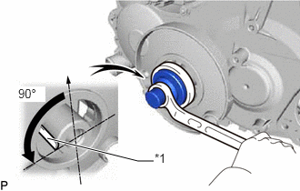
| *1 | Key |
Using the crankshaft pulley bolt, set the No. 1 cylinder to 90° BTDC/compression.
- HINT:
-
Set the No. 1 cylinder to 90° BTDC/compression to prevent the top of the piston from hitting against the valve head.
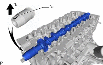
| *a | Key Groove |
| *b | Upward |
Install the camshaft sub-assembly.
Apply engine oil to the thrust portion of the intake camshaft sub-assembly.
Place the intake camshaft sub-assembly on the cylinder head sub-assembly with the key groove facing upward.
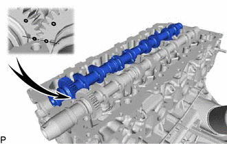
Align the timing marks (1-dot marks) of the camshaft sub-assembly drive and driven main gears and set the exhaust camshaft sub-assembly in place.
Remove any old seal packing (FIPG material) from the No. 1 camshaft bearing cap.
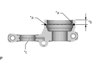
| *a | Seal Packing |
| *b | 8.0 mm (0.315 in.) |
| *c | Oil Passage |
Apply seal packing to the specified areas shown in the illustration.
- Seal packing:
Toyota Genuine Seal Packing Black, Three Bond 1207B or equivalent
- Standard seal diameter:
4 mm (0.157 in.)
- NOTICE:
- ·
Do not allow seal packing to contact the oil passage of the camshaft bearing cap.
·After applying seal packing, install the camshaft bearing caps within 3 minutes and tighten the bolts within 15 minutes.
·Do not start the engine for at least 2 hours after installation.
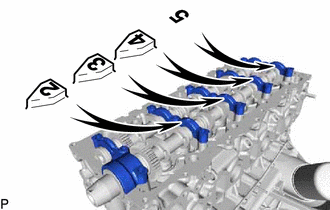
Install the No. 1 camshaft bearing cap, 3 No. 2 camshaft bearing caps and No. 3 camshaft bearing cap to their proper locations from the cylinder head sub-assembly.
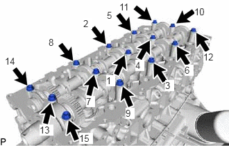
Apply a light coat of engine oil to the threads and under the heads of the camshaft bearing cap bolts.
Install and uniformly tighten the 15 camshaft bearing cap bolts in several passes in the sequence shown in the illustration.
- Torque:
- 19 N*m (194 kgf*cm, 14 ft.*lbf)
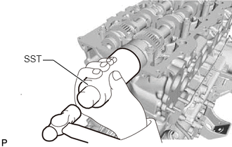
Install a new camshaft oil seal.
Apply MP grease to the lip of a new camshaft oil seal.
Using SST and a hammer, tap in the camshaft oil seal until its surface is flush with the surfaces of the camshaft bearing cap and cylinder head sub-assembly.
- SST
- 09608-06041
11322B
2.INSTALL NO. 2 TIMING BELT COVER
13523P
3.INSTALL CAMSHAFT TIMING PULLEY
13505
4.INSTALL NO. 1 TIMING BELT IDLER SUB-ASSEMBLY
13568
5.INSTALL TIMING BELT
6.INSPECT AND ADJUST VALVE CLEARANCE
11322A
7.INSTALL NO. 1 TIMING BELT COVER
23670
8.INSTALL INJECTOR ASSEMBLY
9.INSPECT FOR FUEL LEAK
11201
10.INSTALL CYLINDER HEAD COVER SUB-ASSEMBLY
23770
11.INSTALL NO. 2 NOZZLE LEAKAGE PIPE ASSEMBLY
23704
12.INSTALL NO. 4 INJECTION PIPE SUB-ASSEMBLY
23701
13.INSTALL NO. 1, NO. 2 AND NO. 3 INJECTION PIPE SUB-ASSEMBLY
15301
14.INSTALL ENGINE OIL LEVEL DIPSTICK GUIDE
17118
15.INSTALL MANIFOLD STAY
17113E
16.INSTALL NO. 1 INTAKE PIPE
16711
17.INSTALL FAN SHROUD
16571C
18.INSTALL NO. 1 RADIATOR HOSE
19.ADD ENGINE OIL
20.BLEED AIR FROM FUEL SYSTEM
21.ADD ENGINE COOLANT
22.INSPECT FOR COOLANT LEAK
23.INSPECT FOR OIL LEAK
24.INSPECT FOR FUEL LEAK
51410
25.INSTALL NO. 1 ENGINE UNDER COVER SUB-ASSEMBLY (for 4WD and Pre-Runner)
26.INSPECT ENGINE OIL LEVEL