INTERIOR PANELS / TRIM LOWER INSTRUMENT PANEL INSTALLATION
CAUTION / NOTICE / HINT
- HINT:
- ·
Use the same procedure for RHD and LHD vehicles.
·The procedure listed below is for LHD vehicles.
·A bolt without a torque specification is shown in the standard bolt chart.
Click hereGeneral>SPECIFICATIONS>STANDARD BOLT>SPECIFIED TORQUE FOR STANDARD BOLTS
PROCEDURE

 55303B
1.INSTALL LOWER INSTRUMENT PANEL SUB-ASSEMBLY
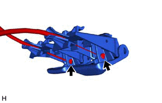
Connect the hood lock control cable and fuel lid lock open cable.
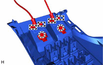
Attach the guide and claw to connect the hood lock control lever sub-assembly and fuel lid lock open lever to the lower instrument panel sub-assembly.
Connect the connector.
Attach the guide to install the lower instrument panel sub-assembly.
Install the 7 screws <B>, 2 bolts <C> and screw <D>.
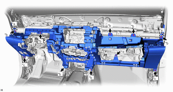
| *a | Guide | *b | Screw <B> |
| *c | Bolt <C> | *d | Screw <D> |
55054
2.INSTALL GLOVE COMPARTMENT DOOR STOPPER SUB-ASSEMBLY
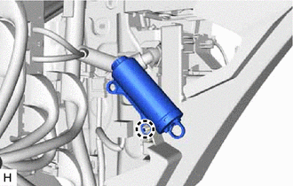
Attach the claw to install the glove compartment door stopper sub-assembly.
55407C
3.INSTALL LOWER INSTRUMENT COVER SUB-ASSEMBLY
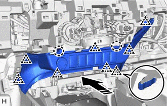

|
Install in this Direction |
Connect the connector.
Attach the clip and claw to install the lower instrument cover sub-assembly as shown in the illustration.
55550
4.INSTALL GLOVE COMPARTMENT DOOR ASSEMBLY
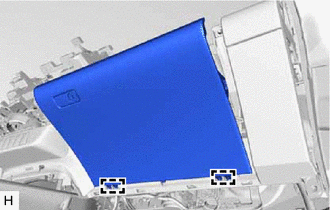
Attach the hinge to install the glove compartment door assembly.
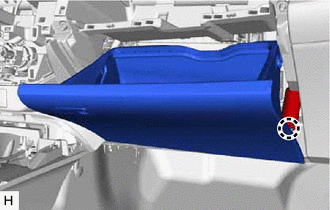
Attach the claw to connect the glove compartment door stopper sub-assembly.
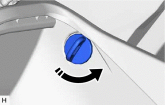
|
|
Install in this Direction |
Install the glove door stopper pin and twist it as shown in the illustration.
- HINT:
-
Use the same procedure for both glove door stopper pins.
55607
5.INSTALL NO. 2 INSTRUMENT PANEL UNDER COVER SUB-ASSEMBLY
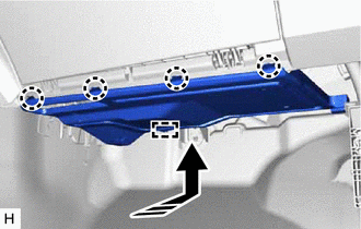
|
|
Install in this Direction |
Attach the guide.
Attach the claw to install the No. 2 instrument panel under cover sub-assembly as shown in the illustration.
73900
6.INSTALL LOWER NO. 1 INSTRUMENT PANEL AIRBAG ASSEMBLY (w/ Knee Airbag)
55606
7.INSTALL NO. 1 INSTRUMENT PANEL UNDER COVER SUB-ASSEMBLY (w/ Knee Airbag)
Attach the claw to connect the DLC3.
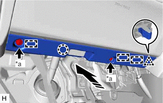
| *a | Screw <A> |
|
|
Install in this Direction |
Attach the guide, claw and clip to install the No. 1 instrument panel under cover sub-assembly as shown in the illustration.
Install the 2 screws <A>.
55045
8.INSTALL LOWER INSTRUMENT PANEL FINISH PANEL SUB-ASSEMBLY (w/o Knee Airbag)
Attach the claw to connect the DLC3.
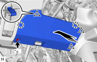
| *a | Screw <A> |
|
|
Install in this Direction |
Attach the clip and claw to install the lower instrument panel finish panel sub-assembly as shown in the illustration.
Install the 2 screws <A>.
55420A
9.INSTALL CENTER INSTRUMENT CLUSTER FINISH PANEL ASSEMBLY
w/o Audio:
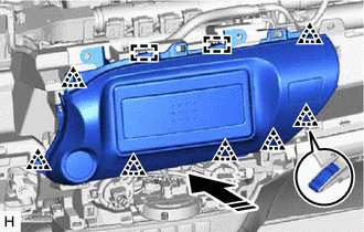
|
|
Install in this Direction |
Connect the connector.
Attach the guide and clip to install the center instrument cluster finish panel assembly as shown in the illustration.
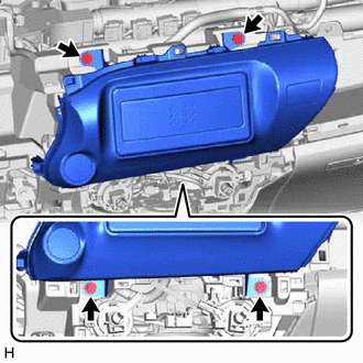
Install the 4 screws.
w/ Audio, for Radio Receiver Type:
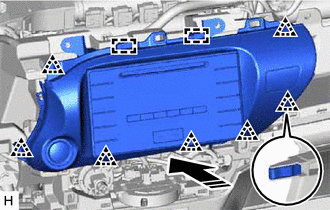
|
|
Install in this Direction |
Connect the connector.
Attach the guide and clip to install the center instrument cluster finish panel assembly as shown in the illustration.
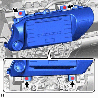
Install the 4 screws.
w/ Audio, for Radio and Display Type:
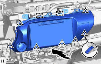
|
|
Install in this Direction |
Connect the connector.
Attach the guide and clip to install the center instrument cluster finish panel assembly as shown in the illustration.
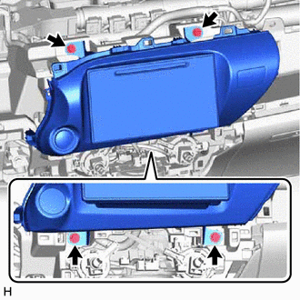
Install the 4 screws.
w/ Audio, for Navigation Receiver Type:
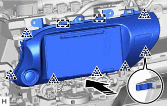
|
|
Install in this Direction |
Connect the connector.
Attach the guide and clip to install the center instrument cluster finish panel assembly as shown in the illustration.
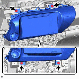
Install the 4 screws.
84013A
10.INSTALL INTEGRATION PANEL SUB-ASSEMBLY (for Manual Air Conditioning System)
55905J
11.INSTALL CONTROL KNOB SUB-ASSEMBLY (for Manual Air Conditioning System)
55900
12.INSTALL AIR CONDITIONING CONTROL ASSEMBLY (for Automatic Air Conditioning System)
84140
13.INSTALL HEADLIGHT DIMMER SWITCH ASSEMBLY
58811A
14.INSTALL FRONT CONSOLE BOX (w/o Console Box Lid)
58901A
15.INSTALL REAR CONSOLE BOX SUB-ASSEMBLY (w/ Rear Console Box)
58810J
16.INSTALL CONSOLE BOX ASSEMBLY (w/ Console Box Lid)
55302A
17.INSTALL UPPER INSTRUMENT PANEL SUB-ASSEMBLY
18.CONNECT CABLE TO NEGATIVE BATTERY TERMINAL
- NOTICE:
-
When disconnecting the cable, some systems need to be initialized after the cable is reconnected.
-
Click hereGeneral>INTRODUCTION>REPAIR INSTRUCTION>INITIALIZATION
19.CHECK SRS WARNING LIGHT