NAVIGATION / MULTI INFO DISPLAY NAVIGATION SYSTEM Illumination Circuit
DESCRIPTION
Power is supplied to the navigation receiver assembly and steering pad switch assembly illumination when the light control switch is in the tail or head position.
WIRING DIAGRAM
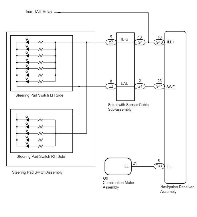
CAUTION / NOTICE / HINT
- CAUTION:
-
The vehicle is equipped with a Supplemental Restraint System (SRS) which includes components such as airbags. Before servicing (including removal or installation of parts), be sure to read the precautionary notice for the Supplemental Restraint System.
- NOTICE:
-
Check that the wire harness is properly installed and does not have any sharp bends, pinching or loose connections.
-
Click hereGeneral>INTRODUCTION>HOW TO TROUBLESHOOT ECU CONTROLLED SYSTEMS>HOW TO PROCEED WITH TROUBLESHOOTING
PROCEDURE
Check if the panel switch of the navigation receiver assembly dims, the screen changes to the night screen, or illumination for the steering pad switch assembly, heater control switch or others (hazard switch, transmission control switch, etc.) comes on when the light control switch is turned to the head or tail position.
- Result:
Result Proceed to Illumination other than that for the steering pad switch assembly properly functions. A Illumination other than that for the navigation receiver assembly properly functions. B Illumination does not function at all (navigation receiver assembly, hazard switch, heater control switch, etc.). C
A
B
C
Disconnect the G41 navigation receiver assembly connector.
Disconnect the G4 spiral with sensor cable sub-assembly connector.
Measure the resistance according to the value(s) in the table below.
- Standard Resistance:
Tester Connection Condition Specified Condition G41-23 (SWG) - G4-3 (EAU) Always Below 1 Ω G41-23 (SWG) - Body ground Always 10 kΩ or higher
Measure the voltage according to the value(s) in the table below.
- Standard Voltage:
Tester Connection Switch Condition Specified Condition G4-13 (IL+2) - Body ground Light control switch in the tail or head position 11 to 14 V
- Result:
Proceed to OK NG
OK
NG
Remove the steering pad switch assembly.
Click hereSteering>STEERING COLUMN>STEERING PAD SWITCH>REMOVAL
Inspect the steering pad switch assembly.
Click hereSteering>STEERING COLUMN>STEERING PAD SWITCH>INSPECTION
- Result:
Proceed to OK NG
OK
NG
Remove the spiral with sensor cable sub-assembly.
Click hereVehicle Interior>SUPPLEMENTAL RESTRAINT SYSTEMS>SPIRAL CABLE>REMOVAL
Inspect the spiral with sensor cable sub-assembly.
Click hereVehicle Interior>SUPPLEMENTAL RESTRAINT SYSTEMS>SPIRAL CABLE>INSPECTION
- Result:
Proceed to OK NG
OK
Click hereAudio / Visual / Telematics>NAVIGATION / MULTI INFO DISPLAY>NAVIGATION SYSTEM>PROBLEM SYMPTOMS TABLE
NG
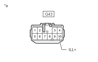
| *a | Front view of wire harness connector
(to Navigation Receiver Assembly) |
Disconnect the navigation receiver assembly connector.
Measure the voltage according to the value(s) in the table below.
- Standard Voltage:
Tester Connection Switch Condition Specified Condition G43-10 (ILL+) - Body ground Light control switch in the tail or head position 11 to 14 V
- Result:
Proceed to OK NG
OK
NG
Disconnect the G44 navigation receiver assembly connector.
Disconnect the G9 combination meter assembly connector.
Measure the resistance according to the value(s) in the table below.
- Standard Resistance:
Tester Connection Condition Specified Condition G44-5 (ILL-) - G9-21 (ILL-) Always Below 1 Ω G44-5 (ILL-) - Body ground Always 10 kΩ or higher
- Result:
Proceed to OK NG
OK
Click hereAudio / Visual / Telematics>NAVIGATION / MULTI INFO DISPLAY>NAVIGATION SYSTEM>PROBLEM SYMPTOMS TABLE
NG