BRAKE CONTROL / DYNAMIC CONTROL SYSTEMS ANTI-LOCK BRAKE SYSTEM ABS Warning Light Remains ON
DESCRIPTION
When one of the following conditions is met, the ABS warning light remains on:
The skid control ECU (brake actuator assembly) connector is disconnected from the skid control ECU (brake actuator assembly).
There is a malfunction in the skid control ECU (brake actuator assembly) internal circuit.
There is an open in the harness between the combination meter and the skid control ECU (brake actuator assembly).
The anti-lock brake system is defective.
WIRING DIAGRAM
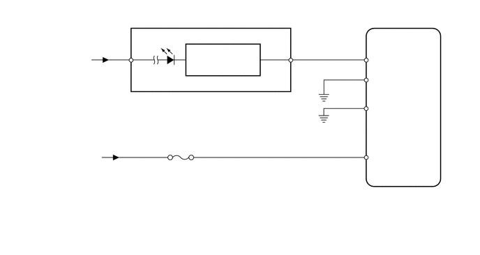
CAUTION / NOTICE / HINT
- NOTICE:
- ·
Inspect the fuses for circuits related to this system before performing the following procedure.
·Before disconnecting the connector, make sure that there are no problems with the connection.
·After disconnecting the connector, make sure that the connector case and terminals are not deformed or corroded.
PROCEDURE
Check if DTCs for the ABS are output.
Click hereBrake>BRAKE CONTROL / DYNAMIC CONTROL SYSTEMS>ANTI-LOCK BRAKE SYSTEM>DTC CHECK / CLEAR
- Chassis > ABS/VSC/TRC > Trouble Codes
- 50001 8
- Result:
Result Proceed to DTC not output A DTC output B
A
B
Click hereBrake>BRAKE CONTROL / DYNAMIC CONTROL SYSTEMS>ANTI-LOCK BRAKE SYSTEM>DIAGNOSTIC TROUBLE CODE CHART
Check if the skid control ECU (brake actuator assembly) connector is securely connected.
- OK:
The connector is securely connected.
- Result:
Proceed to OK NG
OK
NG
Click hereBrake>BRAKE CONTROL / DYNAMIC CONTROL SYSTEMS>ANTI-LOCK BRAKE SYSTEM>C1241/41
- Result:
Proceed to OK NG
OK
NG
Click hereBrake>BRAKE CONTROL / DYNAMIC CONTROL SYSTEMS>ANTI-LOCK BRAKE SYSTEM>C0273/13
- Result:
Proceed to OK NG
OK
NG
Turn the ignition switch off.
Disconnect the skid control ECU (brake actuator assembly) connector.
Disconnect the G19 combination meter connector.
Measure the resistance according to the value(s) in the table below.
- Standard Resistance:
Tester Connection Condition Specified Condition A13-13 (WA) - G19-38 (LP) Always Below 1 Ω .A13-13 (WA) - Body ground Always 10 kΩ or higher
- Result:
Proceed to OK NG
OK
NG
Turn the ignition switch off.
Disconnect the skid control ECU (brake actuator assembly) connector.
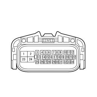
| *a | Front view of wire harness connector
(to Skid Control ECU [Brake Actuator Assembly]) |
Using SST, connect terminals 13 (WA) and 2 (GND1) or 24 (GND2) of the skid control ECU (brake actuator assembly) connector.
- SST
- 09843-18040
Turn the ignition switch to ON.
Check the ABS warning light.
- OK:
ABS warning light turns off.
- Result:
Proceed to OK NG
OK
NG
Click hereVehicle Interior>METER / GAUGE / DISPLAY>METER / GAUGE SYSTEM>HOW TO PROCEED WITH TROUBLESHOOTING