STEERING GEAR / LINKAGE STEERING GEAR INSTALLATION
CAUTION / NOTICE / HINT
- HINT:
- ·
Use the same procedure for RHD and LHD vehicles.
·The procedure listed below is for LHD vehicles.
PROCEDURE

 1.INSTALL POWER STEERING LINK ASSEMBLY
Install the steering link with the 2 bolts and 2 nuts.
- Torque:
- 95 N*m (969 kgf*cm, 70 ft.*lbf)
- HINT:
-
If necessary, return the differential to its original position and install the differential mount.
2.INSTALL FRONT STABILIZER BAR
3.CONNECT STEERING GEAR OUTLET RETURN TUBE
Using a union nut wrench, connect the outlet return tube.
- Torque:
- 44 N*m (449 kgf*cm, 33 ft.*lbf)
- NOTICE:
-
Use the formula to calculate special torque values for situations where a union nut wrench is combined with a torque wrench (See page General>INTRODUCTION>REPAIR INSTRUCTION>PRECAUTION).
Install the hose with the clip.
4.CONNECT PRESSURE FEED TUBE ASSEMBLY
Install the pressure feed tube to the steering link with the bolt.
- Torque:
- 28 N*m (286 kgf*cm, 21 ft.*lbf)
Using a union nut wrench, tighten the flare nut and connect the pressure feed tube.
- Torque:
- 44 N*m (449 kgf*cm, 33 ft.*lbf)
- NOTICE:
-
Use the formula to calculate special torque values for situations where a union nut wrench is combined with a torque wrench (See page General>INTRODUCTION>REPAIR INSTRUCTION>PRECAUTION).
5.CONNECT NO. 2 STEERING INTERMEDIATE SHAFT SUB-ASSEMBLY
Align the matchmarks on the steering intermediate shaft and steering link.
Install the bolt.
- Torque:
- 35 N*m (357 kgf*cm, 26 ft.*lbf)
6.CONNECT STEERING SLIDING YOKE
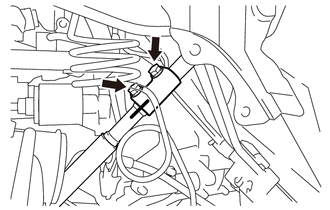
| *1 | Matchmark |
Align the matchmarks on the steering sliding yoke and steering intermediate shaft, and connect the steering sliding yoke to the steering intermediate shaft.
Install the bolt labeled B.
- Torque:
- 35 N*m (357 kgf*cm, 26 ft.*lbf)
Tighten the bolt labeled A.
- Torque:
- 35 N*m (357 kgf*cm, 26 ft.*lbf)
7.CONNECT TIE ROD END SUB-ASSEMBLY LH
Connect the tie rod end to the steering knuckle arm with the nut.
- Torque:
- 49 N*m (500 kgf*cm, 36 ft.*lbf)
Install a new cotter pin.
- NOTICE:
-
If the holes for the cotter pin are not aligned, tighten the nut an additional 60°.
8.CONNECT TIE ROD END SUB-ASSEMBLY RH
- HINT:
-
Use the same procedure described for the LH side.
9.INSTALL FRONT SIDE MEMBER TO FRONT SUSPENSION CROSSMEMBER BRACE
Install the 2 crossmember braces with the 8 bolts.
- Torque:
- 50 N*m (510 kgf*cm, 37 ft.*lbf)
10.INSTALL FRONT SIDE MEMBER TO FRONT SUSPENSION CROSSMEMBER BRACE
Install the 2 crossmember braces with the 10 bolts.
- Torque:
- 50 N*m (510 kgf*cm, 37 ft.*lbf)
11.INSTALL NO. 1 ENGINE UNDER COVER (w/ Engine Under Cover)
- Torque:
- 28 N*m (286 kgf*cm, 21 ft.*lbf)
12.INSTALL FRONT WHEELS
13.ADD POWER STEERING FLUID
14.ADJUST POWER STEERING FLUID
15.CHECK POWER STEERING FLUID LEAK
16.ADJUST FRONT WHEEL ALIGNMENT