Front Power Seat does not Operate with Front Power Seat Switch
Circuit diagnosis · Vehicles built from Aug 2014
Versions by build date: Aug 2013 – Jul 2014 from Aug 2014
DESCRIPTION
When a signal is input into the front power seat switch (seat ECU), the ECU manages the signals received from the front power seat switch and operates each motor. When 2 or more signals are input, the motors only operate when the signals are from the slide switch and reclining switch.WIRING DIAGRAM
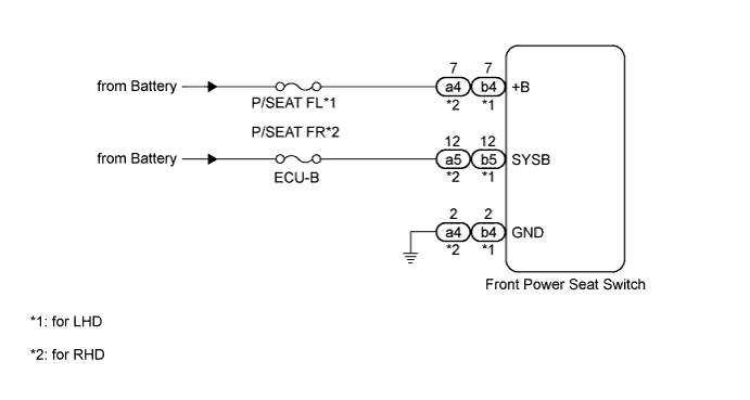

INSPECTION PROCEDURE
- HINT:
- Inspect the fuses for circuits related to this system before performing the following inspection procedure.
| 1. READ VALUE USING INTELLIGENT TESTER (FRONT POWER SEAT SWITCH) |

Using the intelligent tester, read the Data List (Click here).
Driver Seat Tester Display
Measurement Item/Range
Normal Condition
Diagnostic Note
Reclining Rear
Reclining switch signal (Rearward) / ON or OFF
ON: Reclining switch (Rearward) on
OFF: Reclining switch (Rearward) off
-
Reclining Front
Reclining switch signal (Forward) / ON or OFF
ON: Reclining switch (Forward) on
OFF: Reclining switch (Forward) off
-
Front Vertical Down
Front vertical switch signal (Downward) / ON or OFF
ON: Front vertical switch (Downward) on
OFF: Front vertical switch (Downward) off
-
Front Vertical Up
Front vertical switch signal (Upward) / ON or OFF
ON: Front vertical switch (Upward) on
OFF: Front vertical switch (Upward) off
-
Lifter Switch Down
Lifter switch signal (Downward) / ON or OFF
ON: Lifter switch (Downward) on
OFF: Lifter switch (Downward) off
-
Lifter Switch Up
Lifter switch signal (Upward) / ON or OFF
ON: Lifter switch (Upward) on
OFF: Lifter switch (Upward) off
-
Slide Rear
Sliding switch signal (Rearward) / ON or OFF
ON: Sliding switch (Rearward) on
OFF: Sliding switch (Rearward) off
-
Slide Front
Sliding switch signal (Forward) / ON or OFF
ON: Sliding switch (Forward) on
OFF: Sliding switch (Forward) off
-
- OK:
- On intelligent tester screen, each item changes between ON and OFF according to above chart.
|
|
||||

| OK | ||
 |
||
| ||
| 2. CHECK HARNESS AND CONNECTOR (FRONT POWER SEAT SWITCH - BATTERY AND BODY GROUND) |
for LHD:Disconnect the b4 and b5 switch connectors.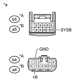
for RHD:Disconnect the a4 and a5 switch connectors.
Measure the voltage according to the value(s) in the table below.
- Standard Voltage:
for LHD Tester Connection
Condition
Specified Condition
b4-7 (+B) - Body ground
Always
11 to 14 V
b5-12 (SYSB) - Body ground
Always
11 to 14 V
for RHD Tester Connection
Condition
Specified Condition
a4-7 (+B) - Body ground
Always
11 to 14 V
a5-12 (SYSB) - Body ground
Always
11 to 14 V
Measure the resistance according to the value(s) in the table below.
- Standard Resistance:
for LHD Tester Connection
Condition
Specified Condition
b4-2 (GND) - Body ground
Always
Below 1 Ω
for RHD Tester Connection
Condition
Specified Condition
a4-2 (GND) - Body ground
Always
Below 1 Ω
| *A |
for LHD |
| *B |
for RHD |
| *a |
Front view of wire harness connector (to Front Power Seat Switch) |
|
|
||||

| OK | ||
|
||
| ||