3.
DISCONNECT CABLE FROM NEGATIVE BATTERY TERMINAL
NOTICE:
After turning the engine switch off, waiting time may be required before disconnecting the cable from the battery terminal. Therefore, make sure to read the disconnecting the cable from the battery terminal notice before proceeding with work (Click here).
When disconnecting the cable, some systems need to be initialized after the cable is reconnected (Click here).
4.
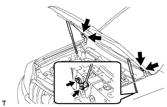
REMOVE HOOD SUB-ASSEMBLY
Disconnect the washer nozzle hose.
Remove the 8 bolts and hood.
NOTICE:
If the hood support is detached from the ball joint, it become non-reusable. Therefore, do not detach the hood support from the ball joint unless replacing it.
5.
REMOVE COWL TOP VENTILATOR LOUVER SUB-ASSEMBLY
Remove the cowl top ventilator louver (Click here).
6.
REMOVE FRONT BUMPER COVER LOWER
Remove the clip, 5 bolts and front bumper cover lower.
7.
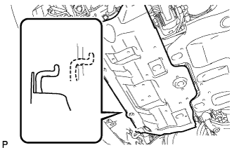
REMOVE NO. 1 ENGINE UNDER COVER SUB-ASSEMBLY
Remove the 4 bolts.
Unhook the engine under cover from the vehicle body as shown in the illustration.
8.
REMOVE TRANSMISSION UNDER COVER
Remove the 2 bolts and transmission under cover.
9.
REMOVE REAR ENGINE UNDER COVER ASSEMBLY
Remove the 4 bolts and rear engine under cover.
10.
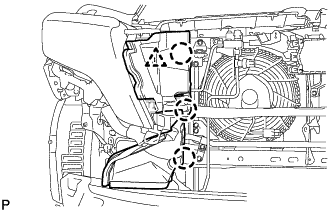
REMOVE FRONT FENDER APRON SEAL LH
Remove the 5 clips and front fender apron seal.
11.
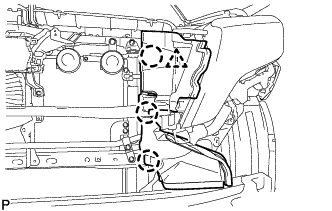
REMOVE FRONT FENDER APRON SEAL RH
Remove the 5 clips and front fender apron seal.
12.
REMOVE FRONT NO. 1 FENDER APRON TO FRAME SEAL LH
Remove the 5 clips and front No. 1 fender apron to frame seal.
13.
REMOVE FRONT NO. 1 FENDER APRON TO FRAME SEAL RH
Remove the 5 clips and front No. 1 fender apron to frame seal.
14.
REMOVE UPPER RADIATOR SUPPORT SEAL
Remove the 13 clips and upper radiator support seal.
15.
DRAIN ENGINE OIL
Remove the oil filler cap.
Remove the oil pan drain plug and drain the engine oil into a container.
Install a new gasket and the oil pan drain plug.
Torque:
40 N*m{
408 kgf*cm
, 30 ft.*lbf
}
16.
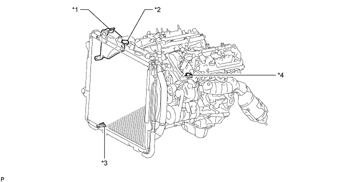
DRAIN ENGINE COOLANT
CAUTION:
Do not remove the radiator cap while the engine and radiator are still hot. Pressurized, hot engine coolant and steam may be released and cause serious burns.
Text in Illustration
*1
Reservoir Cap
*2
Radiator Cap
*3
Radiator Drain Cock Plug
*4
Cylinder Block Drain Cock Plug
Loosen the radiator drain cock plug.
Remove the radiator cap and drain the coolant.
HINT:
Collect the coolant in a container and dispose of it according to the regulations in your area.
Loosen the cylinder block drain cock plug and drain the coolant from the engine.
17.
DISCONNECT CABLE FROM POSITIVE BATTERY TERMINAL
18.
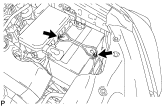
REMOVE BATTERY HOLD DOWN CLAMP
Loosen the 2 nuts and remove the battery hold down clamp.
19.
REMOVE BATTERY
20.
REMOVE BATTERY TRAY
21.
REMOVE V-BANK COVER
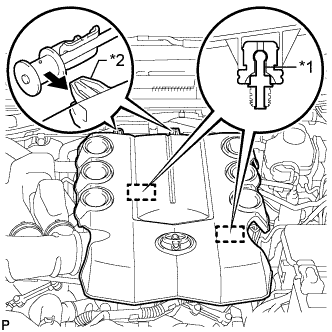
Raise the front of the V-bank cover to detach the 2 pins. Then remove the 2 V-bank cover hooks from the bracket, and remove the V-bank cover.
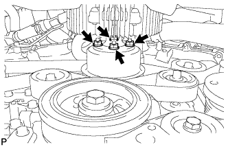
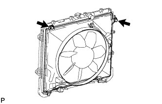
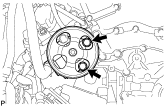
Remove the 4 nuts of the fluid coupling fan, and then remove the shroud together with the coupling fan.
NOTICE:
Be careful not to damage the radiator core.
Remove the fan pulley from the water pump.
34.
REMOVE RADIATOR ASSEMBLY
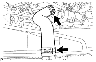
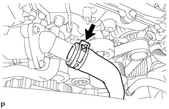
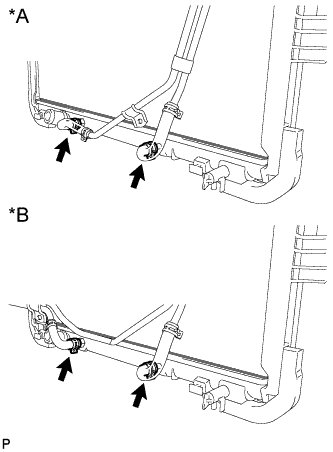
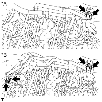
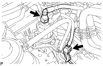
for Automatic Transmission: Disconnect the 2 oil cooler hoses.
Text in Illustration
*A
w/ Warmer
*B
w/ Air Cooled Transmission Oil Cooler
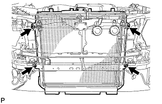
Remove the 4 bolts and radiator.
35.
REMOVE AIR TUBE ASSEMBLY (w/ Secondary Air Injection System)
for Bank 1 Side: Remove the bolt and disconnect the air tube assembly from the emission control valve set.
for Bank 2 Side: Remove the 2 bolts and disconnect the air tube assembly from the No. 2 emission control valve set.
36.
REMOVE INTAKE AIR SURGE TANK
Disconnect the throttle body connector.
Disconnect the No. 4 water by-pass hose.
Disconnect the No. 5 water by-pass hose.
Disconnect the No. 1 fuel vapor feed hose.
Disconnect the No. 1 vacuum switching valve connector.
Disconnect the No. 1 ventilation hose.
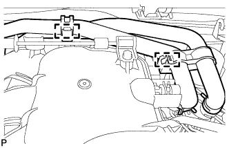
Detach the 2 heater hose clamps.
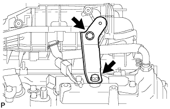
Remove the 2 bolts and throttle body bracket.
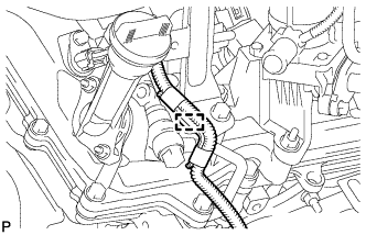
Using a clip remover, detach the wire harness clamp.
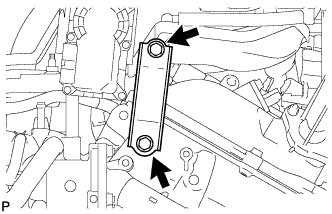
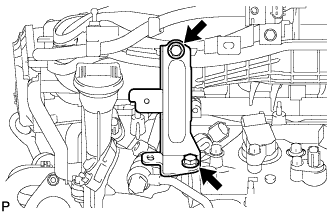
Remove the 2 bolts and No. 1 surge tank stay.
Remove the 2 bolts and No. 2 surge tank stay.
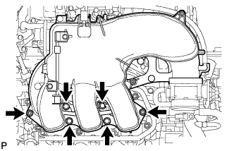
Remove the 2 nuts, 4 bolts and intake air surge tank.
Remove the gasket.
37.
REMOVE FAN AND GENERATOR V BELT
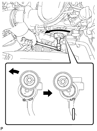
While turning the belt tensioner counterclockwise, align the service hole for the belt tensioner and the belt tensioner fixing position, and then insert a bar of φ 6 mm (0.236 in.) into the service hole to fix the belt tensioner in place.
HINT:
The pulley bolt for the belt tensioner has a left-hand thread.
Remove the V belt.
38.
DISCONNECT VANE PUMP ASSEMBLY
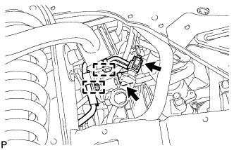
Disconnect the 2 connectors.
Detach the 2 wire harness clamps.
Remove the 2 bolts and disconnect the vane pump.
39.
DISCONNECT DISCHARGE HOSE SUB-ASSEMBLY (w/ Air Conditioning System)
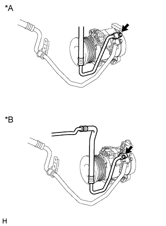
Remove the bolt and disconnect the discharge hose from the cooler compressor.
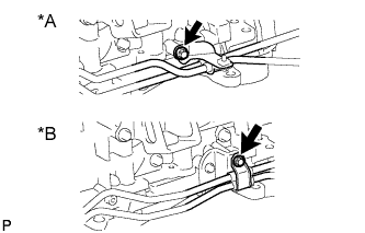
Text in Illustration
*A
except Model Code GRJ150L-GKFEKV, GRJ150L-GKAEKV
*B
Model Code GRJ150L-GKFEKV, GRJ150L-GKAEKV
Remove the O-ring from the discharge hose.
NOTICE:
Seal the openings of the disconnected parts using vinyl tape to prevent moisture and foreign matter from entering them.
40.
DISCONNECT SUCTION HOSE SUB-ASSEMBLY (w/ Air Conditioning System)
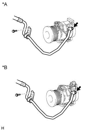
Remove the 2 bolts and disconnect the suction hose from the cooler compressor.
Text in Illustration
*A
except Model Code GRJ150L-GKFEKV, GRJ150L-GKAEKV
*B
Model Code GRJ150L-GKFEKV, GRJ150L-GKAEKV
Remove the O-ring from the suction hose.
NOTICE:
Seal the openings of the disconnected parts using vinyl tape to prevent moisture and foreign matter from entering them.
41.
REMOVE COOLER COMPRESSOR ASSEMBLY (w/ Air Conditioning System)
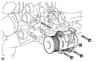
Disconnect the connector.
Remove the 3 bolts, nut and the cooler compressor.
Remove the stud bolt.
42.
REMOVE IDLER PULLEY ASSEMBLY (w/o Air Conditioning System)