1GR-FE ENGINE CONTROL IGNITION COIL AND SPARK PLUG INSTALLATION
CAUTION / NOTICE / HINT
- HINT:
-
for Automatic Transmission:
-
Perform "Inspection After Repairs" after replacing the ignition coil assembly or spark plug (See page Engine / Hybrid System>1GR-FE (ENGINE CONTROL)>SFI SYSTEM>INITIALIZATION).
PROCEDURE

 19100P
1.INSTALL SPARK PLUG
- HINT:
-
for Automatic Transmission:
-
Perform "Inspection After Repairs" after replacing the spark plug (See page Engine / Hybrid System>1GR-FE (ENGINE CONTROL)>SFI SYSTEM>INITIALIZATION).
Install the 6 spark plugs.
- Torque:
- 18 N*m (184 kgf*cm, 13 ft.*lbf)
19500
2.INSTALL IGNITION COIL ASSEMBLY
- HINT:
-
for Automatic Transmission:
-
Perform "Inspection After Repairs" after replacing the ignition coil assembly (See page Engine / Hybrid System>1GR-FE (ENGINE CONTROL)>SFI SYSTEM>INITIALIZATION).
Install the 6 ignition coils with the 6 bolts.
- Torque:
- 10 N*m (102 kgf*cm, 7 ft.*lbf)
Connect the 6 ignition coil connectors.
25702
3.INSTALL NO. 2 EMISSION CONTROL VALVE SET (w/ Secondary Air Injection System)
17362
4.INSTALL NO. 2 AIR TUBE (w/ Secondary Air Injection System)
25701
5.INSTALL EMISSION CONTROL VALVE SET (w/ Secondary Air Injection System)
17361
6.INSTALL AIR TUBE (w/ Secondary Air Injection System)
7.INSTALL AIR CLEANER CASE SUB-ASSEMBLY
8.INSTALL AIR CLEANER CAP AND HOSE
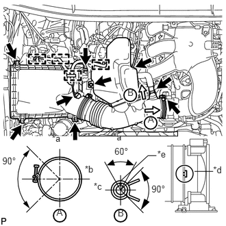
Install the air cleaner cap and hose.
| *a | Top |
| *b | Front |
| *c | RH |
| *d | Align cutout portion of hose with protrusion of throttle |
| *e | Paint Mark |
Install the air cleaner cap and hose with the bolt and fasten the 4 hook clamps.
- Torque:
- 5.0 N*m (51 kgf*cm, 44 in.*lbf)
Tighten the clamp.
- Torque:
- 5.0 N*m (51 kgf*cm, 44 in.*lbf)
Attach the 4 clamps and connect the ventilation hose, vacuum hose and mass air flow meter connector.
- HINT:
-
The direction of the hose clamp is indicated in the illustration.
11259
9.INSTALL V-BANK COVER
53292A
10.INSTALL UPPER RADIATOR SUPPORT SEAL