1KD-FTV ENGINE CONTROL ECD SYSTEM P0191 Fuel Rail Pressure Sensor Circuit Range / Performance
DESCRIPTION
The ECM monitors the internal fuel pressure of the common rail using the fuel pressure sensor, and controls the suction control valve to regulate the common rail pressure so that it reaches the target pressure determined by the ECM. The pressure sensor is a semiconductor that varies its electrical resistance when pressure is applied to its silicon chip. This sensor outputs a voltage in proportion to the common rail fuel pressure.
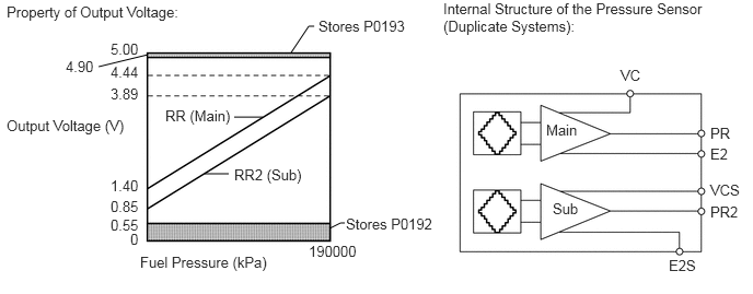
| DTC Detection Drive Pattern | DTC Detection Condition | Trouble Area |
|---|---|---|
| Idling for 1 second | The difference between the main and sub voltage outputs of the fuel pressure sensor is 0.04 V or less, or 1.06 V or higher for 1 second or more (1 trip detection logic). | ·
Open or short in fuel pressure sensor circuit ·
Fuel pressure sensor (common rail) ·
ECM |
| DTC No. | Data List |
|---|---|
| P0191 | ·
Fuel Press ·
Target Common Rail Pressure |
WIRING DIAGRAM
Refer to DTC P0087 (See page Engine / Hybrid System>1KD-FTV (ENGINE CONTROL)>ECD SYSTEM>P0087).
CAUTION / NOTICE / HINT
- NOTICE:
-
After replacing the ECM, the new ECM needs registration (See page Engine / Hybrid System>1KD-FTV (ENGINE CONTROL)>ECD SYSTEM>REGISTRATION) and initialization (See page Engine / Hybrid System>1KD-FTV (ENGINE CONTROL)>ECD SYSTEM>INITIALIZATION).
PROCEDURE
Connect the intelligent tester to the DLC3.
Turn the ignition switch to ON and turn the tester on.
Enter the following menus: Powertrain / Engine and ECT / Data List / Fuel Press and Target Common Rail Pressure.
Start the engine.
Check the change in the values for the data list items above when increasing the engine speed from idling to 3000 rpm with no load.
| Result | Proceed to |
|---|---|
| Fuel Press is always 10000 kPa or less
or Fuel Press is always 200000 kPa or higher |
A |
| Except above | B |
- HINT:
-
Normally, "Fuel Press" is within 15000 kPa of "Target Common Rail Pressure".
A
B
Disconnect the fuel pressure sensor connector.
Disconnect the ECM connector.
Measure the resistance according to the value(s) in the table below.
- Standard Resistance (Check for Open):
Tester Connection Condition Specified Condition C82-5 (PR) - C90-16 (PCR1) Always Below 1 Ω C82-2 (PR2) - C90-2 (PCR2) Always Below 1 Ω C82-1 (VCS) - C90-13 (VCS) Always Below 1 Ω C82-6 (VC) - C90-14 (VCM) Always Below 1 Ω C82-4 (E2) - C90-15 (E2M) Always Below 1 Ω C82-3 (E2S) - C90-8 (E2S) Always Below 1 Ω
- Standard Resistance (Check for Short):
Tester Connection Condition Specified Condition C82-5 (PR) or C90-16 (PCR1) - Body ground Always 10 kΩ or higher C82-2 (PR2) or C90-2 (PCR2) - Body ground Always 10 kΩ or higher C82-1 (VCS) or C90-13 (VCS) - Body ground Always 10 kΩ or higher C82-6 (VC) or C90-14 (VCM) - Body ground Always 10 kΩ or higher C82-4 (E2) or C90-15 (E2M) - Body ground Always 10 kΩ or higher C82-3 (E2S) or C90-8 (E2S) - Body ground Always 10 kΩ or higher
Reconnect the fuel pressure sensor connector.
Reconnect the ECM connector.
OK
NG
Repair or replace the harness or connector.
NEXT
Connect the intelligent tester to the DLC3.
Turn the ignition switch to ON and turn the tester on.
Clear the DTCs (See page Engine / Hybrid System>1KD-FTV (ENGINE CONTROL)>ECD SYSTEM>DTC CHECK / CLEAR).
Let the engine idle for 1 second.
Enter the following menus: Powertrain / Engine and ECT / DTC.
Read the DTCs.
| Result | Proceed to |
|---|---|
| P0191 is output | A |
| No DTC is output | B |
A
B
Replace the common rail (See page Engine / Hybrid System>1KD-FTV (FUEL)>COMMON RAIL>REMOVAL).
NEXT
Bleed the air from the fuel system (See page Engine / Hybrid System>1KD-FTV (FUEL)>FUEL SYSTEM>ON-VEHICLE INSPECTION).
NEXT
Connect the intelligent tester to the DLC3.
Turn the ignition switch to ON and turn the tester on.
Clear the DTCs (See page Engine / Hybrid System>1KD-FTV (ENGINE CONTROL)>ECD SYSTEM>DTC CHECK / CLEAR).
Let the engine idle for 1 second.
Enter the following menus: Powertrain / Engine and ECT / DTC.
Read the DTCs.
| Result | Proceed to |
|---|---|
| P0191 is output | A |
| No DTC is output | B |
A
B
Replace the ECM (See page Engine / Hybrid System>1KD-FTV (ENGINE CONTROL)>ECM>REMOVAL).
NEXT
Connect the intelligent tester to the DLC3.
Turn the ignition switch to ON and turn the tester on.
Clear the DTCs (See page Engine / Hybrid System>1KD-FTV (ENGINE CONTROL)>ECD SYSTEM>DTC CHECK / CLEAR).
Let the engine idle for 1 second.
Enter the following menus: Powertrain / Engine and ECT / DTC.
Confirm that the DTC is not output again.
NEXT