1GD-FTV ENGINE CONTROL ECD SYSTEM(w/ Urea SCR System) P064C Glow Plug Control Module P066B Cylinder 1 Glow Plug Control Circuit High P066D Cylinder 2 Glow Plug Control Circuit High P066F Cylinder 3 Glow Plug Control Circuit High P0671 Cylinder 1 Glow Plug Circuit/Open P0672 Cylinder 2 Glow Plug Circuit/Open P0673 Cylinder 3 Glow Plug Circuit/Open P0674 Cylinder 4 Glow Plug Circuit/Open P067B Cylinder 4 Glow Plug Control Circuit High P166F Glow Plug Control Module Circuit Short
DESCRIPTION
| DTC Detection Drive Pattern | DTC Detection Condition | Trouble Area |
|---|---|---|
| Enter check mode | The MOS inside the glow plug control unit is detected as being stuck on 3 times while the glow plugs are on (2 trip detection logic). | Glow plug controller |
| DTC Detection Drive Pattern | DTC Detection Condition | Trouble Area |
|---|---|---|
| Enter check mode | A short circuit in the No. 1 glow plug circuit is detected 3 times while the glow plugs are on (2 trip detection logic). | ·
Glow plug controller ·
No. 1 glow plug assembly ·
Short in No. 1 glow plug circuit |
| DTC Detection Drive Pattern | DTC Detection Condition | Trouble Area |
|---|---|---|
| Enter check mode | A short circuit in the No. 2 glow plug circuit is detected 3 times while the glow plugs are on (2 trip detection logic). | ·
Glow plug controller ·
No. 2 glow plug assembly ·
Short in No. 2 glow plug circuit |
| DTC Detection Drive Pattern | DTC Detection Condition | Trouble Area |
|---|---|---|
| Enter check mode | A short circuit in the No. 3 glow plug circuit is detected 3 times while the glow plugs are on (2 trip detection logic). | ·
Glow plug controller ·
No. 3 glow plug assembly ·
Short in No. 3 glow plug circuit |
| DTC Detection Drive Pattern | DTC Detection Condition | Trouble Area |
|---|---|---|
| Enter check mode | A short circuit in the No. 4 glow plug circuit is detected 3 times while the glow plugs are on (2 trip detection logic). | ·
Glow plug controller ·
No. 4 glow plug assembly ·
Short in No. 4 glow plug circuit |
| DTC Detection Drive Pattern | DTC Detection Condition | Trouble Area |
|---|---|---|
| Enter check mode | An open circuit in the No. 1 glow plug circuit is detected 3 times while the glow plugs are on (2 trip detection logic). | ·
Glow plug controller ·
No. 1 glow plug assembly ·
Open in No. 1 glow plug circuit |
| DTC Detection Drive Pattern | DTC Detection Condition | Trouble Area |
|---|---|---|
| Enter check mode | An open circuit in the No. 2 glow plug circuit is detected 3 times while the glow plugs are on (2 trip detection logic). | ·
Glow plug controller ·
No. 2 glow plug assembly ·
Open in No. 2 glow plug circuit |
| DTC Detection Drive Pattern | DTC Detection Condition | Trouble Area |
|---|---|---|
| Enter check mode | An open circuit in the No. 3 glow plug circuit is detected 3 times while the glow plugs are on (2 trip detection logic). | ·
Glow plug controller ·
No. 3 glow plug assembly ·
Open in No. 3 glow plug circuit |
| DTC Detection Drive Pattern | DTC Detection Condition | Trouble Area |
|---|---|---|
| Enter check mode | An open circuit in the No. 4 glow plug circuit is detected 3 times while the glow plugs are on (2 trip detection logic). | ·
Glow plug controller ·
No. 4 glow plug assembly ·
Open in No. 4 glow plug circuit |
| DTC Detection Drive Pattern | DTC Detection Condition | Trouble Area |
|---|---|---|
| Enter check mode | A short circuit in a wire harness between the glow plugs is detected 3 times while the glow plugs are on (2 trip detection logic). | ·
Glow plug controller ·
Open or short in glow plug circuit |
WIRING DIAGRAM
Refer to DTC P052F (See page Engine / Hybrid System>1GD-FTV (ENGINE CONTROL)>ECD SYSTEM (w/ Urea SCR System)>P052F)
CAUTION / NOTICE / HINT
- NOTICE:
- ·
Inspect the fuses of circuits related to this system before performing the following inspection procedure.
·After replacing the ECM, the new ECM needs registration (See page Engine / Hybrid System>1GD-FTV (ENGINE CONTROL)>ECD SYSTEM (w/ Urea SCR System)>REGISTRATION) and initialization (See page Engine / Hybrid System>1GD-FTV (ENGINE CONTROL)>ECD SYSTEM (w/ Urea SCR System)>INITIALIZATION).
PROCEDURE
Connect the GTS to the DLC3.
Turn the engine switch on (IG) and turn the GTS on.
Enter the following menus: Powertrain / Engine and ECT / Trouble Codes.
Read the DTCs.
| Result | Proceed to |
|---|---|
| DTC P0671, P0672, P0673 and/or P0674 is output | A |
| DTC P066B, P066D, P066F and/or P067B is output | B |
| DTC P064C and/or P166F is output | C |
A
B
C
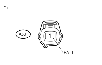
Disconnect the glow plug controller connector.
Measure the voltage according to the value(s) in the table below.
- Standard Voltage:
Tester Connection Condition Specified Condition A80-1 (BATT) - Body ground Always 11 to 14 V
| *a | Front view of wire harness connector
(to Glow Plug Controller) |
Reconnect the glow plug controller connector.
OK
NG
Disconnect connectors of the glow plug controller.
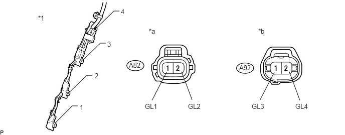
Remove the No. 1 glow plug connector from the glow plug.
Measure the resistance according to the value(s) in the table below.
- Standard Resistance:
Tester Connection Condition Specified Condition A82-1 (GL1) - No. 1 glow plug connector terminal 1 Always Below 1 Ω A82-2 (GL2) - No. 1 glow plug connector terminal 2 Always Below 1 Ω A92-1 (GL3) - No. 1 glow plug connector terminal 3 Always Below 1 Ω A92-2 (GL4) - No. 1 glow plug connector terminal 4 Always Below 1 Ω
| *1 | No. 1 Glow Plug Connector | - | - |
| *a | Front view of wire harness connector
(to Glow Plug Controller) |
*b | Front view of wire harness connector
(to Glow Plug Controller) |
Reconnect the glow plug controller connector.
Reinstall the No. 1 glow plug connector.
OK
NG
Clear the DTCs (See page Engine / Hybrid System>1GD-FTV (ENGINE CONTROL)>ECD SYSTEM (w/ Urea SCR System)>DTC CHECK / CLEAR).
Exchange the glow plugs of the malfunctioning cylinders (the cylinders indicated by output DTCs) with the glow plugs of normally functioning cylinders.
Turn the engine switch on (IG) and turn the GTS on.
Using the GTS, switch the ECM from normal mode to check mode (See page Engine / Hybrid System>1GD-FTV (ENGINE CONTROL)>ECD SYSTEM (w/ Urea SCR System)>CHECK MODE PROCEDURE).
Enter the following menus: Powertrain / Engine and ECT / Trouble Codes.
Read the DTCs.
| Result | Proceed to |
|---|---|
| Same DTCs (that have been erased) | A |
| Other DTCs | B |
- HINT:
-
Check for DTCs in check mode.
B
A
Replace the glow plug assembly (See page Engine / Hybrid System>1GD-FTV (STARTING)>GLOW PLUG>REMOVAL).
NEXT
Repair or replace the harness or connector.
NEXT
Connect the GTS to the DLC3.
Clear the DTCs (See page Engine / Hybrid System>1GD-FTV (ENGINE CONTROL)>ECD SYSTEM (w/ Urea SCR System)>DTC CHECK / CLEAR).
Turn the engine switch off for 30 seconds or more.
Turn the engine switch on (IG) and turn the GTS on.
Using the GTS, switch the ECM from normal mode to check mode (See page Engine / Hybrid System>1GD-FTV (ENGINE CONTROL)>ECD SYSTEM (w/ Urea SCR System)>CHECK MODE PROCEDURE).
Enter the following menus: Powertrain / Engine and ECT / Trouble Codes.
Confirm that the DTC is not output again.
- HINT:
-
Check for DTCs in check mode.
NEXT
Disconnect connectors of the glow plug controller.
Remove the No. 1 glow plug connector from the glow plug.
Measure the resistance according to the value(s) in the table below.
- Standard Resistance:
Tester Connection Condition Specified Condition A82-1 (GL1) or No. 1 glow plug connector terminal 1 - Body ground Always Below 1 Ω A82-2 (GL2) or No. 1 glow plug connector terminal 2 - Body ground Always Below 1 Ω A92-1 (GL3) or No. 1 glow plug connector terminal 3 - Body ground Always Below 1 Ω A92-2 (GL4) or No. 1 glow plug connector terminal 4 - Body ground Always Below 1 Ω
| *1 | No. 1 Glow Plug Connector | - | - |
| *a | Front view of wire harness connector
(to Glow Plug Controller) |
*b | Front view of wire harness connector
(to Glow Plug Controller) |
- HINT:
-
Make sure that there are no short circuits to the battery.
Reconnect the glow plug controller connector.
Reinstall the No. 1 glow plug connector.
OK
NG
Replace the glow plug controller (See page Engine / Hybrid System>1GD-FTV (STARTING)>GLOW PLUG CONTROLLER>REMOVAL).
NEXT
Repair or replace the harness or connector.
NEXT
Connect the GTS to the DLC3.
Clear the DTCs (See page Engine / Hybrid System>1GD-FTV (ENGINE CONTROL)>ECD SYSTEM (w/ Urea SCR System)>DTC CHECK / CLEAR).
Turn the engine switch off for 30 seconds or more.
Turn the engine switch on (IG) and turn the GTS on.
Using the GTS, switch the ECM from normal mode to check mode (See page Engine / Hybrid System>1GD-FTV (ENGINE CONTROL)>ECD SYSTEM (w/ Urea SCR System)>CHECK MODE PROCEDURE).
Enter the following menus: Powertrain / Engine and ECT / Trouble Codes.
Read the DTCs.
- OK:
No DTC is output.
- HINT:
-
Check for DTCs in check mode.
OK
NG
Replace the glow plug assembly (See page Engine / Hybrid System>1GD-FTV (STARTING)>GLOW PLUG>REMOVAL).
NEXT
Disconnect connectors of the glow plug controller.
Remove the No. 1 glow plug connector from the glow plug.
Measure the resistance according to the value(s) in the table below.
- Standard Resistance:
Tester Connection Condition Specified Condition A82-1 (GL1) or No. 1 glow plug connector terminal 1 - Body ground Always Below 1 Ω A82-2 (GL2) or No. 1 glow plug connector terminal 2 - Body ground Always Below 1 Ω A92-1 (GL3) or No. 1 glow plug connector terminal 3 - Body ground Always Below 1 Ω A92-2 (GL4) or No. 1 glow plug connector terminal 4 - Body ground Always Below 1 Ω
| *1 | No. 1 Glow Plug Connector | - | - |
| *a | Front view of wire harness connector
(to Glow Plug Controller) |
*b | Front view of wire harness connector
(to Glow Plug Controller) |
- HINT:
-
Make sure that there are no short circuits to the battery.
Reconnect the glow plug controller connector.
Reinstall the No. 1 glow plug connector.
OK
NG
Replace the glow plug controller (See page Engine / Hybrid System>1GD-FTV (STARTING)>GLOW PLUG CONTROLLER>REMOVAL).
NEXT
Repair or replace the harness or connector.
NEXT
Connect the GTS to the DLC3.
Clear the DTCs (See page Engine / Hybrid System>1GD-FTV (ENGINE CONTROL)>ECD SYSTEM (w/ Urea SCR System)>DTC CHECK / CLEAR).
Turn the engine switch off for 30 seconds or more.
Turn the engine switch on (IG) and turn the GTS on.
Using the GTS, switch the ECM from normal mode to check mode (See page Engine / Hybrid System>1GD-FTV (ENGINE CONTROL)>ECD SYSTEM (w/ Urea SCR System)>CHECK MODE PROCEDURE).
Enter the following menus: Powertrain / Engine and ECT / Trouble Codes.
Confirm that the DTC is not output again.
- HINT:
-
Check for DTCs in check mode.
NEXT
Inspect the GLOW relay (See page Engine / Hybrid System>1GD-FTV (STARTING)>RELAY>ON-VEHICLE INSPECTION).
OK
NG
Disconnect the cable from the negative (-) battery terminal.
Disconnect the cable from the positive (+) battery terminal.
Remove the GLOW relay assembly.
Remove the No. 1 glow plug connector from the glow plug.
Disconnect connectors of the glow plug controller.
Disconnect the ECM connectors.
Measure the resistance according to the value(s) in the table below.
- Standard Resistance:
Tester Connection Condition Specified Condition GLOW relay terminal 5 - Battery positive terminal Always Below 1 Ω GLOW relay terminal 1 - Body ground Always Below 1 Ω GLOW relay terminal 3 - A80-1 (BATT) Always Below 1 Ω GLOW relay terminal 2 - G184-15 (GREL) Always Below 1 Ω GLOW relay terminal 5 or Battery positive terminal - Body ground and other terminals Always 10 kΩ or higher GLOW relay terminal 3 or A80-1 (BATT) - Body ground and other terminals Always 10 kΩ or higher GLOW relay terminal 2 or G184-15 (GREL) - Body ground and other terminals Always 10 kΩ or higher
OK
NG