1KD-FTV EMISSION CONTROL EGR VALVE INSTALLATION
CAUTION / NOTICE / HINT
- NOTICE:
- ·
When replacing the injectors (including shuffling the injectors between the cylinders), common rail or cylinder head, it is necessary to replace the injection pipes with new ones.
·When replacing the fuel supply pump, common rail, cylinder block, cylinder head, cylinder head gasket or timing gear case, it is necessary to replace the fuel inlet pipe with a new one.
PROCEDURE

 25630
1.INSTALL NO. 2 EGR VALVE ASSEMBLY (w/ EGR Cooler)
Using a 6 mm hexagon wrench, install the EGR valve adapter, No. 2 EGR valve, EGR cooler, 2 new gaskets, 3 plate washers with the 3 hexagon bolts.
- Torque:
- 28 N*m (286 kgf*cm, 21 ft.*lbf)
Using a 5 mm hexagon wrench, install the bolt labeled A.
- Torque:
- 13 N*m (133 kgf*cm, 10 ft.*lbf)
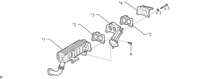
| *1 | EGR Cooler with Pipe | *2 | New Gasket |
| *3 | No. 2 EGR Valve | *4 | EGR Valve Adapter |
25601
2.INSTALL EGR COOLER WITH PIPE (w/ EGR Cooler)
Install a new gasket and the EGR cooler with pipe to the electric EGR control valve and No. 2 EGR valve with the 2 bolts.
- Torque:
- 13 N*m (133 kgf*cm, 10 ft.*lbf)
- HINT:
-
Make sure the claws of the gasket face the electric EGR control valve.
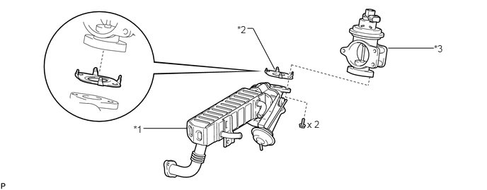
| *1 | EGR Cooler with Pipe and No. 2 EGR Valve | *2 | New Gasket |
| *3 | Electric EGR Control Valve | - | - |
25800
3.TEMPORARILY INSTALL ELECTRIC EGR CONTROL VALVE ASSEMBLY (w/ EGR Cooler)
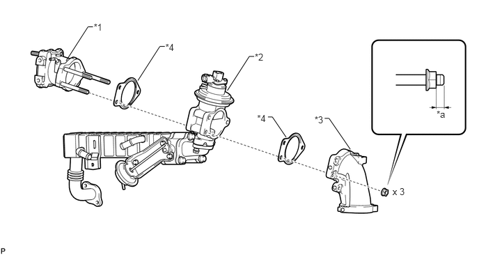
Place a new gasket, the electric EGR control valve, another new gasket and the intake air connector onto the stud bolts of the No. 2 intake air connector and temporarily install the 3 nuts.
- NOTICE:
-
Temporarily install the nuts so that 0 to 2 threads of each stud bolt are visible as shown in the illustration.
 1.402,0.322 1.574,0.505 0.172,0.184 10 *1 3.847,1.683 4.018,1.867 0.172,0.184 10 *4 2.474,0.623 2.646,0.807 0.172,0.184 10 *4 4.706,1.708 4.877,1.866 0.172,0.158 10 *3 6.532,1.62 6.704,1.778 0.172,0.158 10 *a 5.872,2.782 6.094,2.948 0.222,0.166 10 x 3 0.988,0.91 1.316,0.401 1.316,0.401 1.39,0.401 false 2.063,1.203 2.391,0.694 2.391,0.694 2.466,0.694 false 3.812,0.773 3.983,0.957 0.172,0.184 10 *2 3.401,1.353 3.729,0.844 3.729,0.844 3.803,0.844 false 4.281,2.051 4.074,1.748 4.074,1.748 4.009,1.748 false 5.241,2.232 4.922,1.769 4.922,1.769 4.857,1.769 false
| *1 | No. 2 Intake Air Connector | *2 | Electric EGR Control Valve |
| *3 | Intake Air Connector | *4 | New Gasket |
| *a | 0 to 2 threads | - | - |
Set a new gasket on the intake manifold.
- HINT:
-
Make sure the claws of the gasket face the intake manifold.
Temporarily install the intake air connector to the intake manifold with the 3 bolts in the illustration.
Temporarily install the EGR cooler with pipe and new gasket to the cylinder head with the bolt and 2 nuts.
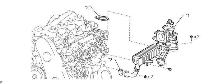
| *1 | Electric EGR Control Valve | *2 | New Gasket |
Connect the No. 2 vacuum transmitting hose to the No. 2 EGR valve.
25800
4.TIGHTEN ELECTRIC EGR CONTROL VALVE ASSEMBLY (w/ EGR Cooler)
Tighten the 3 nuts labeled A in the illustration.
- Torque:
- 20 N*m (204 kgf*cm, 15 ft.*lbf)
Tighten the 3 bolts labeled B in the illustration.
- Torque:
- 20 N*m (204 kgf*cm, 15 ft.*lbf)
- NOTICE:
-
Tighten the bolts in the order shown in the illustration.
Tighten the bolt labeled C in the illustration.
- Torque:
- 22 N*m (224 kgf*cm, 16 ft.*lbf)
Tighten the 2 nuts labeled D in the illustration.
- Torque:
- 13 N*m (133 kgf*cm, 10 ft.*lbf)
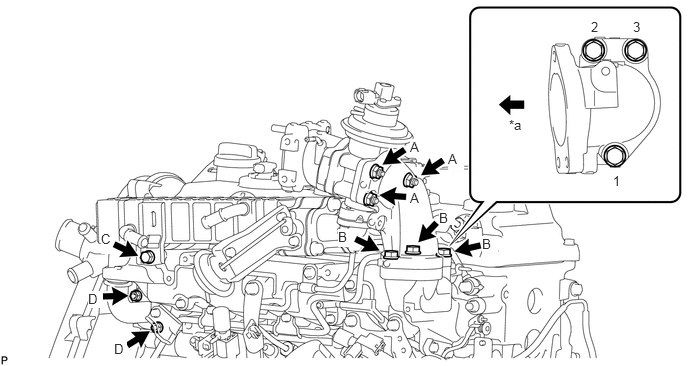
| *a | Front | - | - |
25601
5.INSTALL NO. 1 EGR PIPE SUB-ASSEMBLY (w/o EGR Cooler)
Install a new gasket and the No. 1 EGR pipe to the electric EGR control valve with the 2 bolts.
- Torque:
- 13 N*m (133 kgf*cm, 10 ft.*lbf)
- HINT:
-
Make sure the claws of the gasket face the electric EGR control valve.
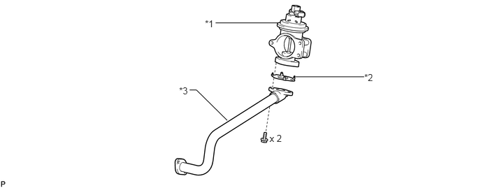
| *1 | Electric EGR Control Valve | *2 | New Gasket |
| *3 | No. 1 EGR Pipe | - | - |
25800
6.TEMPORARILY INSTALL ELECTRIC EGR CONTROL VALVE ASSEMBLY (w/o EGR Cooler)
Place a new gasket, the electric EGR control valve, another new gasket and the intake air connector onto the stud bolts of the No. 2 intake air connector and temporarily install the 3 nuts.
- NOTICE:
-
Temporarily install the nuts so that 0 to 2 threads of each stud bolt are visible as shown in the illustration.
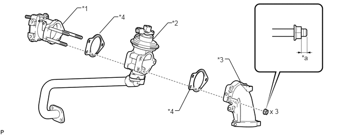
| *1 | No. 2 Intake Air Connector | *2 | Electric EGR Control Valve |
| *3 | Intake Air Connector | *4 | New Gasket |
| *a | 0 to 2 threads | - | - |
Set a new gasket on the intake manifold.
- HINT:
-
Make sure the claws of the gasket face the intake manifold.
Temporarily install the intake air connector to the intake manifold with the 3 bolts.
Temporarily install the No. 1 EGR pipe and a new gasket to the cylinder head with the 2 nuts.
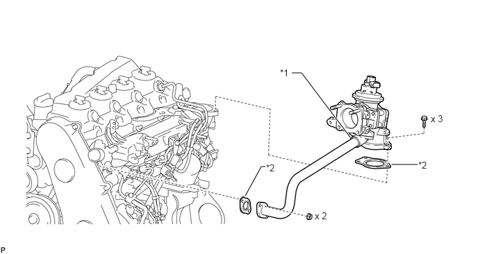
| *1 | Electric EGR Control Valve | *2 | New Gasket |
25800
7.TIGHTEN ELECTRIC EGR CONTROL VALVE ASSEMBLY (w/o EGR Cooler)
Tighten the 3 nuts labeled A in the illustration.
- Torque:
- 20 N*m (204 kgf*cm, 15 ft.*lbf)
Tighten the 3 bolts labeled B in the illustration.
- Torque:
- 20 N*m (204 kgf*cm, 15 ft.*lbf)
- NOTICE:
-
Tighten the bolts in the order shown in the illustration.
Tighten the 2 nuts labeled C in the illustration.
- Torque:
- 13 N*m (133 kgf*cm, 10 ft.*lbf)
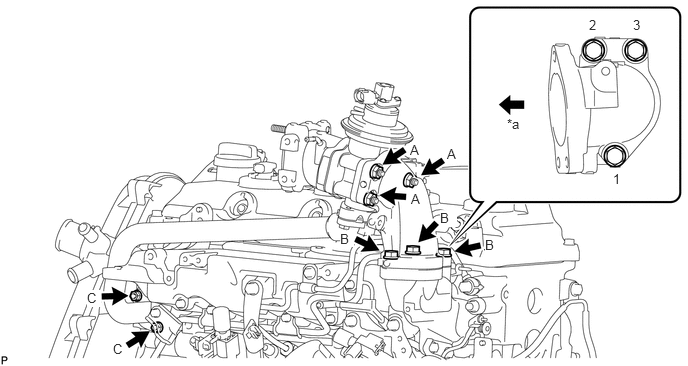
| *a | Front | - | - |
17871A
8.INSTALL AIR CONNECTOR STAY
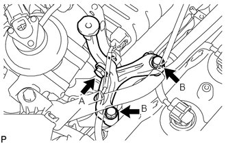
Temporarily install the air connector stay with the 3 bolts.
Tighten the bolt labeled A.
- Torque:
- 20 N*m (204 kgf*cm, 15 ft.*lbf)
Tighten the 2 bolts labeled B.
- Torque:
- 20 N*m (204 kgf*cm, 15 ft.*lbf)
9.INSTALL ELECTRIC VACUUM REGULATING VALVE ASSEMBLY
Install the E-VRV bracket with the 2 bolts.
- Torque:
- 20 N*m (204 kgf*cm, 15 ft.*lbf)
Install the gas filter and the gas filter bracket with the bolt.
- Torque:
- 20 N*m (204 kgf*cm, 15 ft.*lbf)
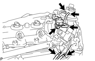
Connect the 5 vacuum hoses.
| *1 | Yellow Mark |
| *2 | Pink Mark |
- NOTICE:
-
Install the vacuum hoses so that they completely cover the pipes.
Connect the 2 connectors to the electric EGR control valve and E-VRV.
Attach the wire harness clamp.
25625
10.INSTALL EGR VALVE BRACKET
Install the EGR valve bracket with the 2 nuts.
- Torque:
- 8.0 N*m (82 kgf*cm, 71 in.*lbf)
82121
11.CONNECT ENGINE WIRE (for LHD)
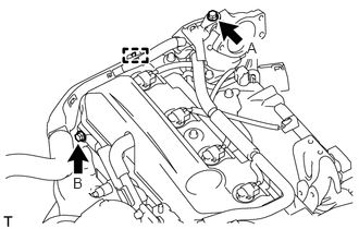
Attach the clamp.
Connect the engine wire with the 2 bolts.
- Torque:
- for bolt A : 13 N*m (131 kgf*cm, 9 ft.*lbf)
- for bolt B : 22 N*m (220 kgf*cm, 16 ft.*lbf)
82121
12.CONNECT ENGINE WIRE (for RHD)
Connect the engine wire with the bolt.
- Torque:
- 13 N*m (131 kgf*cm, 9 ft.*lbf)
13.INSTALL INJECTION PIPE
- NOTICE:
- ·
When replacing an injector, it is necessary to replace the 4 injection pipes with new ones.
·Keep the joints of the injection pipe clean.
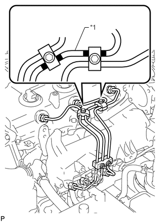
Temporarily install the No. 1, No. 2 and No. 3 injection pipes with the union nuts.
| *1 | No. 2 Injection Pipe |
Install the No. 2 and No. 3 injection pipe clamps with the 2 bolts and 2 nuts as shown in the illustration.
- Torque:
- 5.0 N*m (51 kgf*cm, 44 in.*lbf)
- HINT:
-
If the painted mark on the No. 2 injection pipe has disappeared, use the illustration as a reference to install the clamps.
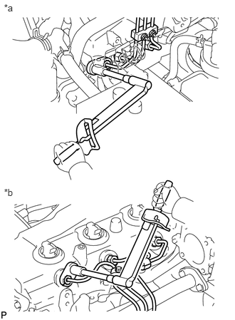
Using a 17 mm union nut wrench, tighten the injection pipe union nuts on the common rail side.
- Torque:
- 35 N*m (357 kgf*cm, 26 ft.*lbf)
| *a | for Common Rail Side |
| *b | for Injector Side |
- NOTICE:
-
Use the formula to calculate special torque values for situations where a union nut wrench is combined with a torque wrench (See page General>INTRODUCTION>REPAIR INSTRUCTION>PRECAUTION).
Using a 17 mm union nut wrench, tighten the injection pipe union nuts on the injector side.
- Torque:
- 35 N*m (357 kgf*cm, 26 ft.*lbf)
- NOTICE:
-
Use the formula to calculate special torque values for situations where a union nut wrench is combined with a torque wrench (See page General>INTRODUCTION>REPAIR INSTRUCTION>PRECAUTION).
16281
14.CONNECT NO. 4 WATER BY-PASS HOSE (w/ EGR Cooler)
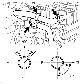
Connect the No. 4 water by-pass hose to the EGR cooler.
| *1 | Lower Side |
| *2 | Upper Side |
| *3 | LH Side of Vehicle |
- HINT:
- ·
The direction of the hose clamp is indicated in the illustration.
·Insert the outlet hose into the stopper.
16267
15.CONNECT NO. 3 WATER BY-PASS HOSE (w/ EGR Cooler)
Connect the No. 3 water by-pass hose to the EGR cooler.
- HINT:
- ·
The direction of the hose clamp is indicated in the illustration.
·Insert the outlet hose into the stopper.
Install the clamp.
26100G
16.INSTALL DIESEL THROTTLE BODY ASSEMBLY
Install the diesel throttle body (See page Engine / Hybrid System>1KD-FTV (ENGINE CONTROL)>DIESEL THROTTLE BODY>INSTALLATION).
55781E
17.INSTALL COWL TOP VENTILATOR LOUVER SUB-ASSEMBLY
Install the cowl top ventilator louver (See page Vehicle Exterior>WIPER / WASHER>FRONT WIPER MOTOR>INSTALLATION).
28800
18.CONNECT CABLE TO NEGATIVE BATTERY TERMINAL
- NOTICE:
-
When disconnecting the cable, some systems need to be initialized after the cable is reconnected (See page General>INTRODUCTION>REPAIR INSTRUCTION>INITIALIZATION).
19.ADD ENGINE COOLANT (w/ EGR Cooler)
20.INSPECT FOR COOLANT LEAK (w/ EGR Cooler)
21.BLEED AIR FROM FUEL SYSTEM
22.INSPECT FOR FUEL LEAK
51405A
23.INSTALL NO. 1 ENGINE UNDER COVER SUB-ASSEMBLY
52129B
24.INSTALL FRONT BUMPER LOWER COVER