CRUISE CONTROL DRIVING SUPPORT ECU INSTALLATION
CAUTION / NOTICE / HINT
- NOTICE:
- ·
Do not twist the connectors of the driving support ECU when connecting them.
·Do not apply more force than necessary to the connectors. If more than 98 N (10 kgf, 22 lbf) of force is applied to a connector, the connector or connector holder may be damaged.
- HINT:
- ·
A bolt without a torque specification is shown in the standard bolt chart (See page General>SPECIFICATIONS>STANDARD BOLT>SPECIFIED TORQUE FOR STANDARD BOLTS).
·Use the same procedure for RHD and LHD vehicles.
·The procedure listed below is for LHD vehicles.
PROCEDURE

 88150A
1.INSTALL DRIVING SUPPORT ECU ASSEMBLY
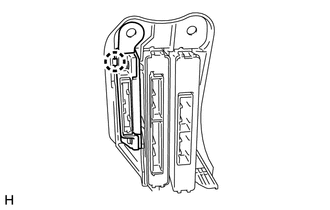
Attach the claw to install the driving support ECU assembly.
- NOTICE:
-
When a new ECU is installed, perform initialization (See page Engine / Hybrid System>CRUISE CONTROL>DRIVING SUPPORT ECU>INITIALIZATION).
82877
2.INSTALL ECU INTEGRATION BOX RH
87201B
3.INSTALL NO. 2 AIR DUCT SUB-ASSEMBLY
55550
4.INSTALL GLOVE COMPARTMENT DOOR ASSEMBLY
55607
5.INSTALL NO. 2 INSTRUMENT PANEL UNDER COVER SUB-ASSEMBLY
55461A
6.INSTALL INSTRUMENT PANEL ORNAMENT
55317A
7.INSTALL INSTRUMENT SIDE PANEL RH
62111C
8.INSTALL COWL SIDE TRIM BOARD RH
Attach the clip and claw to install the cowl side trim board.
Install the clip.
67910
9.INSTALL DOOR SCUFF PLATE ASSEMBLY RH
Attach the 4 clips, 10 claws and 2 guides to install the door scuff plate.