AC60F AUTOMATIC TRANSMISSION / TRANSAXLE OIL COOLER(for 1GR-FE) INSTALLATION
PROCEDURE

 15710
1.INSTALL OIL COOLER ASSEMBLY (w/ Air Cooled Transmission Oil Cooler)
Install the 2 oil cooler brackets to the oil cooler assembly with the 2 bolts.
- Torque:
- 5.5 N*m (56 kgf*cm, 49 in.*lbf)
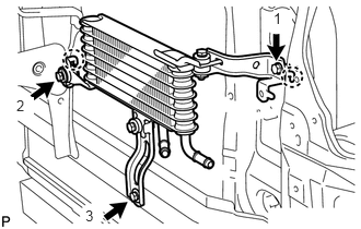
Attach the 2 claws and install the oil cooler assembly to the vehicle body with the 3 bolts in the order shown in the illustration.
- Torque:
- 5.5 N*m (56 kgf*cm, 49 in.*lbf)
32907C
2.INSTALL NO. 3 OIL COOLER TUBE SUB-ASSEMBLY (w/ Air Cooled Transmission Oil Cooler)
Pass the No. 3 oil cooler tube sub-assembly through the hole of vehicle body from the rear of the vehicle and install it to the oil cooler bracket with the bolt.
- Torque:
- 5.5 N*m (56 kgf*cm, 49 in.*lbf)
32943A
3.INSTALL NO. 6 INLET OIL COOLER HOSE AND NO.6 OUTLET OIL COOLER HOSE (w/ Air Cooled Transmission Oil Cooler)
- NOTICE:
- ·
When disconnecting the hoses from the tube, support the tube by hand and be careful to prevent the tube from being deformed.
·Make sure to install the clips so that the spool fitting is not overlapped.
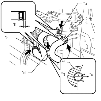
Install the No. 6 oil cooler inlet hose and No. 6 oil cooler outlet hose to the oil cooler, and slide the 2 clips to secure them.
| *a | Blue Paint Mark |
| *b | Pink Paint Mark |
| *c | Yellow Paint Mark |
| *d | White Paint Mark |
| *e | Front Side |
| *f | No hose clamp claw in this region |
| *g | 205° |
| *h | 2 to 7 mm (0.0788 to 0.2755 in.) |
- NOTICE:
-
Make sure to install any hose clips without a specific installation direction in a direction that does not interfere with other parts.
Connect the No. 6 oil cooler inlet hose and No. 6 oil cooler outlet hose to the No. 3 oil cooler tube sub-assembly, and slide the 2 clips to secure them.
- NOTICE:
-
Make sure to install any hose clips without a specific installation direction in a direction that does not interfere with other parts.
32907D
4.INSTALL NO. 2 OIL COOLER TUBE SUB-ASSEMBLY
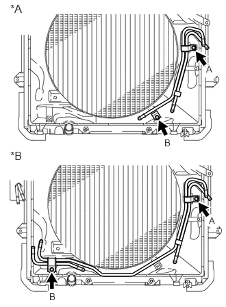
Temporarily install the oil cooler tube to the fan shroud with bolt labeled A. Install bolt labeled B and tighten it to the specified torque. Then tighten bolt labeled A to the specified torque.
- Torque:
- 5.5 N*m (56 kgf*cm, 49 in.*lbf)
| *A | w/o Air Cooled Transmission Oil Cooler |
| *B | w/ Air Cooled Transmission Oil Cooler |
32943
5.INSTALL NO. 5 OIL COOLER INLET HOSE AND NO. 5 OIL COOLER OUTLET HOSE (w/ Air Cooled Transmission Oil Cooler)
- NOTICE:
- ·
When disconnecting the hoses from the tube, support the tube by hand and be careful to prevent the tube from being deformed.
·Make sure to install the clips so that the spool fitting is not overlapped.
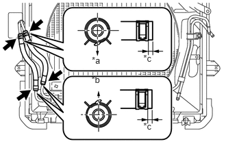
Install the No. 5 oil cooler inlet hose and No. 5 oil cooler outlet hose to the No. 2 oil cooler tube sub-assembly, and slide the 2 clips to secure them.
| *a | Rear Side |
| *b | Front Side |
| *c | 2 to 7 mm (0.0788 to 0.2755 in.) |
Connect the No. 5 oil cooler inlet hose and No. 5 oil cooler outlet hose to the No. 3 oil cooler tube sub-assembly, and slide the 2 clips to secure them.
32941A
6.INSTALL NO. 4 OIL COOLER INLET HOSE AND NO. 4 OIL COOLER OUTLET HOSE
- NOTICE:
- ·
When disconnecting the hoses from the tube, support the tube by hand and be careful to prevent the tube from being deformed.
·Make sure to install the clips so that the spool fitting is not overlapped.
Install the No. 4 oil cooler inlet hose and No. 4 oil cooler outlet hose to the No. 2 oil cooler tube, and slide the 2 clips to secure them.
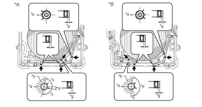
| *A | w/o Air Cooled Transmission Oil Cooler | *B | w/ Air Cooled Transmission Oil Cooler |
| *a | Rear Side | *b | No hose clamp claw in this region |
| *c | 90° | *d | 17.6° |
| *e | 130° | *f | 33.2° |
| *g | 2 to 7 mm (0.0788 to 0.2755 in.) | - | - |
Connect the No. 4 oil cooler inlet hose and No. 4 oil cooler outlet hose to the radiator, and slide the 2 clips to secure them.
- NOTICE:
-
Make sure to install any hose clips without a specific installation direction in a direction that does not interfere with other parts.
32921
7.INSTALL NO. 1 OIL COOLER INLET TUBE AND NO. 1 OIL COOLER OUTLET TUBE (w/o Air Cooled Transmission Oil Cooler)
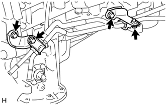
Install the 2 oil cooler tube clamps to the automatic transmission assembly and engine assembly with the 2 bolts.
- Torque:
- 14 N*m (143 kgf*cm, 10 ft.*lbf)
Install the No. 1 oil cooler inlet tube, No. 1 oil cooler outlet tube and 2 flexible hose clamps to the 2 oil cooler tube clamps with the 2 bolts.
- Torque:
- 5.5 N*m (56 kgf*cm, 49 in.*lbf)
32921
8.INSTALL NO. 1 OIL COOLER INLET TUBE AND NO. 1 OIL COOLER OUTLET TUBE (w/ Air Cooled Transmission Oil Cooler)
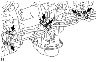
Install the 2 oil cooler tube clamps to the automatic transmission and engine assembly with the 2 bolts.
- Torque:
- 14 N*m (143 kgf*cm, 10 ft.*lbf)
Connect the ends of the No. 1 oil cooler inlet tube and No. 1 oil cooler outlet tube to the automatic transmission assembly by hand.
Close the 2 oil cooler tube clamps and install the 2 bolts.
- Torque:
- 5.5 N*m (56 kgf*cm, 49 in.*lbf)
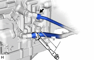
Using a 17 mm union nut wrench, tighten the No. 1 oil cooler inlet tube and No. 1 oil cooler outlet tube.
- Torque:
- Specified tightening torque : 34 N*m (350 kgf*cm, 25 ft.*lbf)
| *a | Torque Wrench Fulcrum Length |
- HINT:
- ·
Calculate the torque wrench reading when changing the fulcrum length of the torque wrench.
(See page General>INTRODUCTION>REPAIR INSTRUCTION>PRECAUTION)
·When using a union nut wrench (fulcrum length of 30 mm (1.181 in.)) + torque wrench (fulcrum length of 180 mm (7.087 in.)): 29 N*m (300 kgf*cm, 22 ft.*lbf)
32941
9.INSTALL NO. 3 OIL COOLER INLET HOSE AND NO. 3 OIL COOLER OUTLET HOSE
- NOTICE:
- ·
When disconnecting the hoses from the tube, support the tube by hand and be careful to prevent the tube from being deformed.
·Make sure to install the clips so that the spool fitting is not overlapped.
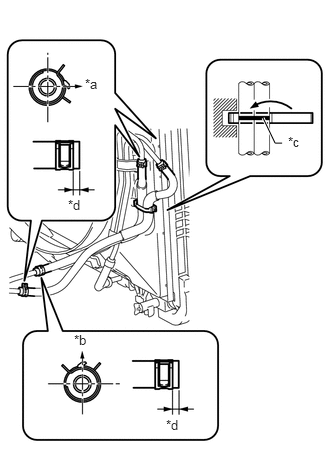
Install the No. 3 oil cooler inlet hose and No. 3 oil cooler outlet hose to the No. 1 oil cooler inlet tube and No. 1 oil cooler outlet tube, and slide the 2 clips to secure them.
| *a | RH Side |
| *b | Upper Side |
| *c | Paint Mark |
| *d | 2 to 7 mm (0.0788 to 0.2755 in.) |
Connect the No. 3 oil cooler inlet hose and No. 3 oil cooler outlet hose to the No. 2 oil cooler tube sub-assembly, and slide the 2 clips to secure them.
Then pass the No. 3 oil cooler inlet hose and No. 3 oil cooler outlet hose through the clamp and close the clamp.
33490F
10.INSTALL TRANSMISSION OIL COOLER ASSEMBLY (w/o Air Cooled Transmission Oil Cooler)
- NOTICE:
-
Make sure to install the clips so that the spool fitting is not overlapped.
Coat 2 new O-rings with ATF, and install them to the transmission oil cooler assembly.
Align the transmission oil cooler with the transmission oil thermostat and assemble them with the 3 bolts.
- Torque:
- 14 N*m (143 kgf*cm, 10 ft.*lbf)
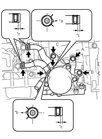
Temporarily install the transmission oil cooler together with the transmission oil thermostat with bolt labeled A. Install bolts labeled B and labeled C and tighten them to the specified torque. Then tighten bolt labeled A to the specified torque.
- Torque:
- 21 N*m (214 kgf*cm, 15 ft.*lbf)
| *a | Front Side |
| *b | Rear Side |
| *c | 2 to 7 mm (0.0788 to 0.2755 in.) |
Install the No. 1 oil cooler inlet hose and No. 1 oil cooler outlet hose to the transmission oil thermostat, and slide the 2 clips to secure them.
Connect the No. 1 oil cooler inlet hose and No. 1 oil cooler outlet hose to the automatic transmission assembly, and slide the 2 clips to secure them.
- NOTICE:
-
Make sure to install any hose clips without a specific installation direction in a direction that does not interfere with other parts.
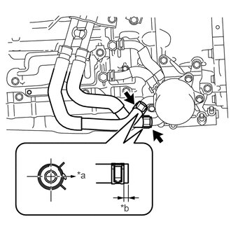
Connect the 2 water by-pass hoses to the transmission oil cooler assembly, and slide the 2 clips to secure them.
| *a | RH Side |
| *b | 2 to 7 mm (0.0788 to 0.2755 in.) |
32943
11.INSTALL NO. 2 OIL COOLER INLET HOSE AND NO. 2 OIL COOLER OUTLET HOSE (w/o Air Cooled Transmission Oil Cooler)
- NOTICE:
- ·
When disconnecting the hoses from the tube, support the tube by hand and be careful to prevent the tube from being deformed.
·Make sure to install the clips so that the spool fitting is not overlapped.
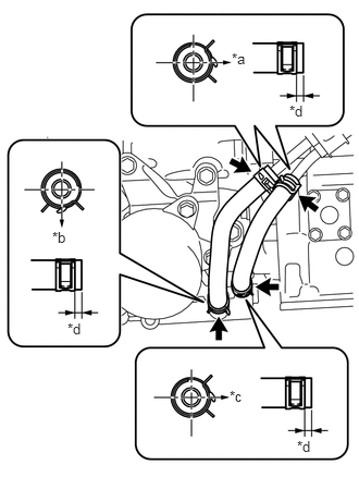
Install the No. 2 oil cooler inlet hose and No. 2 oil cooler outlet hose to the transmission oil thermostat, and slide the 2 clips to secure them.
| *a | RH Side |
| *b | Lower Side |
| *c | Front Side |
| *d | 2 to 7 mm (0.0788 to 0.2755 in.) |
Connect the No. 2 oil cooler inlet hose and No. 2 oil cooler outlet hose to the No. 1 oil cooler inlet tube and No. 1 oil cooler outlet tube, and slide the 2 clips to secure them.
17104
12.INSTALL EXHAUST MANIFOLD SUB-ASSEMBLY RH
13.ADD ENGINE COOLANT (w/o Air Cooled Transmission Oil Cooler)
14.ADJUST AUTOMATIC TRANSMISSION FLUID LEVEL
15.INSPECT FOR COOLANT LEAK
52119A
16.INSTALL FRONT BUMPER COVER (w/ Air Cooled Transmission Oil Cooler)
51405A
17.INSTALL NO. 1 ENGINE UNDER COVER SUB-ASSEMBLY
51450
18.INSTALL REAR ENGINE UNDER COVER ASSEMBLY