Home › Audio / Visual / Telematics › NAVIGATION / MULTI INFO DISPLAY › NAVIGATION SYSTEM (for Radio and Display Type) › 2016.08–2020.08
RM27T0E _56 Audio / Visual / Telematics _053721 NAVIGATION / MULTI INFO DISPLAY _0260992 NAVIGATION SYSTEM(for Radio and Display Type) J

NAVIGATION / MULTI INFO DISPLAY  NAVIGATION SYSTEM(for Radio and Display Type)  Microphone Circuit between Microphone and Radio Receiver  


DESCRIPTION

w/o Telematics Transceiver

The radio and display receiver assembly and map telephone microphone assembly are connected to each other using the microphone connection detection signal lines.

Using this circuit, the radio and display receiver assembly sends power to the telephone microphone assembly, and the telephone microphone assembly sends microphone signals to the radio and display receiver assembly.


w/ Telematics Transceiver

The radio and display receiver assembly and telephone microphone assembly are connected to each other using the microphone connection detection signal lines.

Using this circuit, the telematics transceiver sends power to the telephone microphone assembly, and the telephone microphone assembly sends microphone signals to the radio and display receiver assembly via the telematics transceiver.


WIRING DIAGRAM
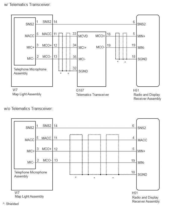
E355982E02
0.177,0.083 4.948,0.323 4.771,0.24 12 false w/ Telematics Transceiver: 0.573,2.813 1.99,3.208 1.417,0.396 10 false Telephone Microphone Assembly 1.792,0.823 2.323,1.083 0.531,0.26 10 false SNS2 2.24,0.823 2.771,1.083 0.531,0.26 10 false 14 1.76,1.333 2.24,1.573 0.479,0.24 10 false MACC 2.24,1.333 2.771,1.594 0.531,0.26 10 false 11 1.771,1.813 2.25,2.052 0.479,0.24 10 false MCO+ 1.781,2.281 2.26,2.521 0.479,0.24 10 false MCO- 2.24,1.813 2.771,2.073 0.531,0.26 10 false 12 2.24,2.281 2.771,2.542 0.531,0.26 10 false 13 3.281,1.427 3.76,1.667 0.479,0.24 10 false MCVD 3.292,1.906 3.771,2.146 0.479,0.24 10 false MCI+ 3.292,2.385 3.771,2.625 0.479,0.24 10 false MCI- 3.292,2.896 3.771,3.135 0.479,0.24 10 false SGND 4,1.417 4.479,1.656 0.479,0.24 10 false MCO+ 4.031,1.885 4.51,2.125 0.479,0.24 10 false MCO- 5.76,1.427 6.24,1.667 0.479,0.24 10 false MIN+ 5.771,1.906 6.25,2.146 0.479,0.24 10 false MIN- 5.75,0.927 6.229,1.167 0.479,0.24 10 false SNS2 5.771,2.385 6.25,2.625 0.479,0.24 10 false SGND 4.479,1.344 5.01,1.604 0.531,0.26 10 false 18 4.479,1.813 5.01,2.073 0.531,0.26 10 false 19 3.042,1.323 3.573,1.583 0.531,0.26 10 false 33 3.052,1.802 3.583,2.063 0.531,0.26 10 false 34 3.052,2.292 3.583,2.552 0.531,0.26 10 false 35 3.052,2.771 3.583,3.031 0.531,0.26 10 false 32 5.573,0.833 6.104,1.094 0.531,0.26 10 false 6 5.573,1.323 6.104,1.583 0.531,0.26 10 false 5 5.521,1.802 6.052,2.063 0.531,0.26 10 false 19 5.521,2.281 6.052,2.542 0.531,0.26 10 false 18 0.521,3.854 1.885,4.177 1.365,0.323 10 false Map Light Assembly 3.188,3.875 4.74,4.188 1.552,0.313 10 false Telematics Transceiver 5.604,3.875 6.948,4.292 1.344,0.417 10 false Radio and Display Receiver Assembly 5.583,3.698 6.063,3.938 0.479,0.24 10 false H51 0.531,3.677 1.01,3.917 0.479,0.24 10 false W7 3.188,3.698 3.667,3.938 0.479,0.24 10 false G187 1.531,1.333 2.063,1.594 0.531,0.26 10 false 5 1.531,1.802 2.063,2.063 0.531,0.26 10 false 3 1.542,2.281 2.073,2.542 0.531,0.26 10 false 2 1.521,0.823 2.052,1.083 0.531,0.26 10 false 1 1.073,0.927 1.604,1.188 0.531,0.26 10 false SNS2 1.042,1.417 1.521,1.656 0.479,0.24 10 false MACC 1.115,1.896 1.594,2.135 0.479,0.24 10 false MIC+ 1.135,2.365 1.615,2.604 0.479,0.24 10 false MIC- 0.167,4.438 4.938,4.677 4.771,0.24 12 false w/o Telematics Transceiver: 2.521,3.01 2.76,3.208 0.24,0.198 10 false * 4.906,2.521 5.146,2.719 0.24,0.198 10 false * 5.219,2.542 5.458,2.74 0.24,0.198 10 false * 2.833,3.021 3.073,3.219 0.24,0.198 10 false * 3.146,7.365 3.385,7.563 0.24,0.198 10 false * 3.927,7.385 4.167,7.583 0.24,0.198 10 false * 4.708,7.385 4.948,7.583 0.24,0.198 10 false * 0.625,8.135 1.99,8.458 1.365,0.323 10 false Map Light Assembly 0.615,7.979 1.094,8.219 0.479,0.24 10 false W7 1.146,6.708 1.625,6.948 0.479,0.24 10 false MIC- 1.125,6.24 1.604,6.479 0.479,0.24 10 false MIC+ 1.042,5.771 1.521,6.01 0.479,0.24 10 false MACC 1.073,5.26 1.604,5.521 0.531,0.26 10 false SNS2 1.792,5.177 2.323,5.438 0.531,0.26 10 false SNS2 1.74,5.698 2.219,5.938 0.479,0.24 10 false MACC 1.76,6.146 2.24,6.385 0.479,0.24 10 false MCO+ 1.802,6.625 2.281,6.865 0.479,0.24 10 false MCO- 2.25,5.177 2.781,5.438 0.531,0.26 10 false 14 2.26,5.688 2.792,5.948 0.531,0.26 10 false 11 2.26,6.156 2.792,6.417 0.531,0.26 10 false 12 2.271,6.625 2.802,6.885 0.531,0.26 10 false 13 5.76,5.271 6.24,5.51 0.479,0.24 10 false SNS2 5.771,6.719 6.25,6.958 0.479,0.24 10 false MIN- 5.76,6.24 6.24,6.479 0.479,0.24 10 false MIN+ 5.771,5.781 6.25,6.021 0.479,0.24 10 false MACC 5.771,7.219 6.25,7.458 0.479,0.24 10 false SGND 5.5,7.125 6.031,7.385 0.531,0.26 10 false 18 5.5,6.635 6.031,6.896 0.531,0.26 10 false 19 5.552,6.146 6.083,6.406 0.531,0.26 10 false 5 5.552,5.677 6.083,5.938 0.531,0.26 10 false 4 5.542,5.177 6.073,5.438 0.531,0.26 10 false 6 1.521,5.188 2.052,5.448 0.531,0.26 10 false 1 1.531,5.677 2.063,5.938 0.531,0.26 10 false 5 1.542,6.146 2.073,6.406 0.531,0.26 10 false 3 1.552,6.625 2.083,6.885 0.531,0.26 10 false 2 0.594,7.125 2.01,7.521 1.417,0.396 10 false Telephone Microphone Assembly 5.542,8.177 6.885,8.594 1.344,0.417 10 false Radio and Display Receiver Assembly 5.531,7.99 6.01,8.229 0.479,0.24 10 false H51 0.125,8.448 0.906,8.698 0.781,0.25 10 false *: Shielded

CAUTION / NOTICE / HINT

HINT:

When replacing telematics transceiver, perform the vehicle contract setting.

Click hereAudio / Visual / Telematics>NAVIGATION / MULTI INFO DISPLAY>NAVIGATION SYSTEM (for Radio and Display Type)>PRECAUTION


PROCEDURE

1.CONFIRM MODEL
a.

Choose the model to be inspected.

Model:
Model Proceed to
w/o Telematics Transceiver A
w/ Telematics Transceiver B


A

2.CHECK HARNESS AND CONNECTOR (RADIO AND DISPLAY RECEIVER ASSEMBLY - MAP LIGHT ASSEMBLY)

B

5.CHECK HARNESS AND CONNECTOR (RADIO AND DISPLAY RECEIVER ASSEMBLY - MAP LIGHT ASSEMBLY)
2.CHECK HARNESS AND CONNECTOR (RADIO AND DISPLAY RECEIVER ASSEMBLY - MAP LIGHT ASSEMBLY)
a.

Disconnect the H51 radio and display receiver assembly connector.


b.

Disconnect the W7 map light assembly connector.


c.

Measure the resistance according to the value(s) in the table below.

Standard Resistance:
Tester Connection Condition Specified Condition
H51-5 (MIN+) - W7-12 (MCO+) Always Below 1 Ω
H51-4 (MACC) - W7-11 (MACC) Always Below 1 Ω
H51-19 (MIN-) - W7-13 (MCO-) Always Below 1 Ω
H51-6 (SNS2) - W7-14 (SNS2) Always Below 1 Ω
H51-5 (MIN+) - Body ground Always 10 kΩ or higher
H51-18 (SGND) - Body ground Always 10 kΩ or higher
H51-4 (MACC) - Body ground Always 10 kΩ or higher
H51-19 (MIN-) - Body ground Always 10 kΩ or higher
H51-6 (SNS2) - Body ground Always 10 kΩ or higher


Result:
Proceed to
OK
NG


OK

3.INSPECT MAP LIGHT ASSEMBLY

NG

REPAIR OR REPLACE HARNESS OR CONNECTOR

3.INSPECT MAP LIGHT ASSEMBLY
a.

Remove the map light assembly.

Click hereVehicle Interior>LIGHTING (INT)>ROOM LIGHT(for Front)>REMOVAL


b.

Remove the telephone microphone assembly.

Click hereAudio / Visual / Telematics>AUDIO / VIDEO>MICROPHONE AMPLIFIER>REMOVAL
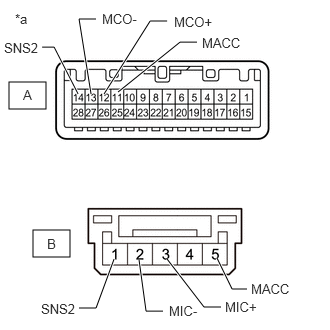

c.
E355979C01
0.094,0.854 0.479,1.135 0.385,0.281 0.344,2.396 0.729,2.677 0.385,0.281 1.229,0.958 1.875,0.438 1.875,0.438 2.052,0.438 true 0.948,0.979 0.823,0.198 0.823,0.198 1,0.198 true 2.26,2.688 2.417,3.01 2.417,3.01 2.573,3.01 true 1.74,2.698 2.125,3.198 2.125,3.198 2.302,3.198 true 0.438,0.49 0.563,0.49 0.563,0.49 0.813,0.979 true 1.083,0.979 1.563,0.219 1.563,0.219 1.74,0.219 true 1.448,2.708 1.521,3.24 1.521,3.24 1.698,3.24 true 1.188,2.698 1,3.208 1,3.208 0.823,3.208 true 0.156,0.115 0.469,0.313 0.313,0.198 10 false *a 0.24,0.906 0.448,1.125 0.208,0.219 10 false A 0.49,2.458 0.698,2.677 0.208,0.219 10 false B 2.615,2.927 3.052,3.135 0.438,0.208 10 false MACC 2.104,0.365 2.542,0.573 0.438,0.208 10 false MACC 1.813,0.146 2.292,0.365 0.479,0.219 10 false MCO+ 1.063,0.115 1.542,0.333 0.479,0.219 10 false MCO- 2.344,3.115 2.823,3.333 0.479,0.219 10 false MIC+ 1.76,3.156 2.24,3.375 0.479,0.219 10 false MIC- 0.042,0.417 0.521,0.635 0.479,0.219 10 false SNS2 0.427,3.135 0.906,3.354 0.479,0.219 10 false SNS2
*a Component without harness connected
(Map Light Assembly)


Measure the resistance according to the value(s) in the table below.

Standard Resistance:
Tester Connection Condition Specified Condition
A-11 (MACC) - B-5 (MACC) Always Below 1 Ω
A-12 (MCO+) - B-3 (MIC+) Always Below 1 Ω
A-13 (MCO-) - B-2 (MIC-) Always Below 1 Ω
A-14 (SNS2) - B-1 (SNS2) Always Below 1 Ω
A-11 (MACC) - A-12 (MCO+) Always 10 kΩ or higher
A-11 (MACC) - A-13 (MCO-) Always 10 kΩ or higher
A-11 (MACC) - A-14 (SNS2) Always 10 kΩ or higher
A-12 (MCO+) - A-13 (MCO-) Always 10 kΩ or higher
A-12 (MCO+) - A-14 (SNS2) Always 10 kΩ or higher
A-13 (MCO-) - A-14 (SNS2) Always 10 kΩ or higher


Result:
Proceed to
OK
NG


OK

4.CHECK TELEPHONE MICROPHONE ASSEMBLY

NG

4.CHECK TELEPHONE MICROPHONE ASSEMBLY
a.

Replace the telephone microphone assembly with a new known good one.

Click hereAudio / Visual / Telematics>AUDIO / VIDEO>MICROPHONE AMPLIFIER>REMOVAL


b.

Check that the malfunction disappears.

OK:

Malfunction disappears.


Result:
Proceed to
OK
NG


OK

END (TELEPHONE MICROPHONE ASSEMBLY IS DEFECTIVE)

NG

5.CHECK HARNESS AND CONNECTOR (RADIO AND DISPLAY RECEIVER ASSEMBLY - MAP LIGHT ASSEMBLY)
a.

Disconnect the H51 radio and display receiver assembly connector.


b.

Disconnect the W7 map light assembly connector.
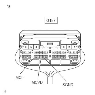

c.

Measure the resistance according to the value(s) in the table below.

Standard Resistance:
Tester Connection Condition Specified Condition
H51-6 (SNS2) - W7-14 (SNS2) Always Below 1 Ω
H51-6 (SNS2) - Body ground Always 10 kΩ or higher


Result:
Proceed to
OK
NG


OK

6.CHECK HARNESS AND CONNECTOR (RADIO AND DISPLAY RECEIVER ASSEMBLY - TELEMATICS TRANSCEIVER)

NG

REPAIR OR REPLACE HARNESS OR CONNECTOR

6.CHECK HARNESS AND CONNECTOR (RADIO AND DISPLAY RECEIVER ASSEMBLY - TELEMATICS TRANSCEIVER)
a.

Disconnect the H51 radio and display receiver assembly connector.


b.

Disconnect the G187 telematics transceiver connector.


c.

Measure the resistance according to the value(s) in the table below.

Standard Resistance:
Tester Connection Condition Specified Condition
H51-5 (MIN+) - G187-18 (MCO+) Always Below 1 Ω
H51-19 (MIN-) - G187-19 (MCO-) Always Below 1 Ω
H51-5 (MIN+) - Body ground Always 10 kΩ or higher
H51-19 (MIN-) - Body ground Always 10 kΩ or higher
H51-18 (SGND) - Body ground Always 10 kΩ or higher


Result:
Proceed to
OK
NG


OK

7.CHECK HARNESS AND CONNECTOR (TELEMATICS TRANSCEIVER - MAP LIGHT ASSEMBLY)

NG

REPAIR OR REPLACE HARNESS OR CONNECTOR

7.CHECK HARNESS AND CONNECTOR (TELEMATICS TRANSCEIVER - MAP LIGHT ASSEMBLY)
a.

Disconnect the G187 telematics transceiver connector.

Click hereAudio / Visual / Telematics>TELEMATICS>TELEMATICS TRANSCEIVER>REMOVAL


b.

Disconnect the W7 map light assembly connector.


c.

Measure the resistance according to the value(s) in the table below.

Standard Resistance:
Tester Connection Condition Specified Condition
G187-33 (MCVD) - W7-11 (MACC) Always Below 1 Ω
G187-34 (MCI+) - W7-12 (MCO+) Always Below 1 Ω
G187-35 (MCI-) - W7-13 (MCO-) Always Below 1 Ω
G187-33 (MCVD) - Body ground Always 10 kΩ or higher
G187-34 (MCI+) - Body ground Always 10 kΩ or higher
G187-35 (MCI-) - Body ground Always 10 kΩ or higher
G187-32 (SGND) - Body ground Always 10 kΩ or higher


Result:
Proceed to
OK
NG


OK

8.INSPECT MAP LIGHT ASSEMBLY

NG

REPAIR OR REPLACE HARNESS OR CONNECTOR

8.INSPECT MAP LIGHT ASSEMBLY
a.

Remove the map light assembly.

Click hereVehicle Interior>LIGHTING (INT)>ROOM LIGHT(for Front)>REMOVAL


b.

Remove the telephone microphone assembly.

Click hereAudio / Visual / Telematics>AUDIO / VIDEO>MICROPHONE AMPLIFIER>REMOVAL


c.
E355979C01
0.094,0.854 0.479,1.135 0.385,0.281 0.344,2.396 0.729,2.677 0.385,0.281 1.229,0.958 1.875,0.438 1.875,0.438 2.052,0.438 true 0.948,0.979 0.823,0.198 0.823,0.198 1,0.198 true 2.26,2.688 2.417,3.01 2.417,3.01 2.573,3.01 true 1.74,2.698 2.125,3.198 2.125,3.198 2.302,3.198 true 0.438,0.49 0.563,0.49 0.563,0.49 0.813,0.979 true 1.083,0.979 1.563,0.219 1.563,0.219 1.74,0.219 true 1.448,2.708 1.521,3.24 1.521,3.24 1.698,3.24 true 1.188,2.698 1,3.208 1,3.208 0.823,3.208 true 0.156,0.115 0.469,0.313 0.313,0.198 10 false *a 0.24,0.906 0.448,1.125 0.208,0.219 10 false A 0.49,2.458 0.698,2.677 0.208,0.219 10 false B 2.615,2.927 3.052,3.135 0.438,0.208 10 false MACC 2.104,0.365 2.542,0.573 0.438,0.208 10 false MACC 1.813,0.146 2.292,0.365 0.479,0.219 10 false MCO+ 1.063,0.115 1.542,0.333 0.479,0.219 10 false MCO- 2.344,3.115 2.823,3.333 0.479,0.219 10 false MIC+ 1.76,3.156 2.24,3.375 0.479,0.219 10 false MIC- 0.042,0.417 0.521,0.635 0.479,0.219 10 false SNS2 0.427,3.135 0.906,3.354 0.479,0.219 10 false SNS2
*a Component without harness connected
(Map Light Assembly)


Measure the resistance according to the value(s) in the table below.

Standard Resistance:
Tester Connection Condition Specified Condition
A-11 (MACC) - B-5 (MACC) Always Below 1 Ω
A-12 (MCO+) - B-3 (MIC+) Always Below 1 Ω
A-13 (MCO-) - B-2 (MIC-) Always Below 1 Ω
A-14 (SNS2) - B-1 (SNS2) Always Below 1 Ω
A-11 (MACC) - A-12 (MCO+) Always 10 kΩ or higher
A-11 (MACC) - A-13 (MCO-) Always 10 kΩ or higher
A-11 (MACC) - A-14 (SNS2) Always 10 kΩ or higher
A-12 (MCO+) - A-13 (MCO-) Always 10 kΩ or higher
A-12 (MCO+) - A-14 (SNS2) Always 10 kΩ or higher
A-13 (MCO-) - A-14 (SNS2) Always 10 kΩ or higher


Result:
Proceed to
OK
NG


OK

9.CHECK TELEMATICS TRANSCEIVER

NG

9.CHECK TELEMATICS TRANSCEIVER
a.

Disconnect the W7 map light assembly connector.


b.
E283057C22
1.625,0.615 2.073,0.854 0.448,0.24 0.729,2.677 1.24,2.073 true 1.365,2.865 1.49,2.063 true 2.406,2.938 1.583,2.083 true 0.24,0.135 0.552,0.292 0.313,0.156 10 false *a 0.563,2.719 0.958,2.875 0.396,0.156 10 false MCI- 1.146,2.896 1.646,3.073 0.5,0.177 10 false MCVD 2.26,2.979 2.76,3.156 0.5,0.177 10 false SGND 1.677,0.656 2.177,0.833 0.5,0.177 10 false G187
*a Component with harness connected
(Telematics Transceiver)


Measure the voltage according to the value(s) in the table below.

Standard Voltage:
Tester Connection Switch Condition Specified Condition
G187-33 (MCVD) - Body ground Engine switch on (ACC) 4 to 6 V


c.

Measure the resistance according to the value(s) in the table below.

Standard Resistance:
Tester Connection Condition Specified Condition
G187-32 (SGND) - Body ground Always Below 1 Ω
G187-35 (MCI-) - Body ground Always Below 1 Ω


Result:
Proceed to
OK
NG


OK

10.CHECK TELEPHONE MICROPHONE ASSEMBLY

NG

10.CHECK TELEPHONE MICROPHONE ASSEMBLY
a.

Replace the telephone microphone assembly with a new known good one.

Click hereAudio / Visual / Telematics>AUDIO / VIDEO>MICROPHONE AMPLIFIER>REMOVAL


b.

Check that the malfunction disappears.

OK:

Malfunction disappears.


Result:
Proceed to
OK
NG


OK

END (TELEPHONE MICROPHONE ASSEMBLY IS DEFECTIVE)

NG