VF4BM TRANSFER / 4WD / AWD TRANSFER SYSTEM P17AA Transfer Shift Motor Control Circuit High
DESCRIPTION
This DTC is output when a short to B+ in the high-low transfer shift motor, center differential lock shift motor and differential lock shift motor* drive circuit is detected.
*: w/ Rear Differential Lock
| DTC No. | DTC Detection Condition
1.
Diagnosis Condition 2.
Malfunction Status 3.
Malfunction Time 4.
Other |
Trouble Area |
|---|---|---|
| P17AA | 1.
While the ignition switch is turned to ON or directly after the ignition switch is turned to ON (high-low transfer shift motor, center differential lock shift motor and differential lock shift motor* not operating) 2.
Short to B+ in the high-low transfer shift motor, center differential lock shift motor and differential lock shift motor* drive circuits 3.
0.5 seconds or more (if directly after ignition switch is turned ON, 0.05 seconds) 4.
1 trip detection logic |
·
Wire harness and connector ·
4 wheel drive control ECU ·
Transfer shift actuator assembly ·
Differential lock shift actuator* |
*: w/ Rear Differential Lock
WIRING DIAGRAM
Refer to DTC P17A9 (See page Drivetrain>VF4BM (TRANSFER / 4WD / AWD)>TRANSFER SYSTEM>P17A9).
PROCEDURE
Disconnect the G54 4 wheel drive control ECU connector.
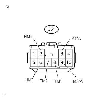
Measure the voltage according to the value(s) in the table below
- Standard Voltage:
Transfer Shift Actuator Assembly (High-low Transfer Shift Motor) Side Tester Connection Condition Specified Condition G54-2 (HM1) or G54-6 (HM2) - Body ground Ignition switch ON Below 1 V
Transfer Shift Actuator Assembly (Center Differential Lock Shift Motor) Side Tester Connection Condition Specified Condition G54-8 (TM1) or G54-7 (TM2) - Body ground Ignition switch ON Below 1 V
Differential Lock Shift Actuator (Differential Lock Shift Motor) Side (w/ Rear Differential Lock) Tester Connection Condition Specified Condition G54-3 (M1) or G54-9 (M2) - Body ground Ignition switch ON Below 1 V
| *A | w/ Rear Differential Lock |
| *a | Front view of wire harness connector
(to 4 Wheel Drive Control ECU) |
- Result:
Result Proceed to OK A NG (transfer shift actuator assembly (high-low transfer shift motor) side) B NG (transfer shift actuator assembly (center differential lock shift motor) side) C NG (differential lock shift actuator (differential lock shift motor) side (w/ Rear Differential Lock)) D
A
B
C
D
Disconnect the G54 4 wheel drive control ECU connector.
Disconnect the C43 transfer shift actuator assembly connector.
Measure the voltage according to the value(s) in the table below.
- Standard Voltage:
Tester Connection Condition Specified Condition G54-2 (HM1) or C43-8 (HM1) - Body ground Ignition switch ON Below 1 V G54-6 (HM2) or C43-7 (HM2) - Body ground Ignition switch ON Below 1 V
OK
NG
Disconnect the G54 4 wheel drive control ECU connector.
Disconnect the C43 transfer shift actuator assembly connector.
Measure the voltage according to the value(s) in the table below.
- Standard Voltage:
Tester Connection Condition Specified Condition G54-8 (TM1) or C43-2 (TM1) - Body ground Ignition switch ON Below 1 V G54-7 (TM2) or C43-1 (TM2) - Body ground Ignition switch ON Below 1 V
OK
NG
Disconnect the G54 4 wheel drive control ECU connector.
Disconnect the E1 differential lock shift actuator connector.
Measure the voltage according to the value(s) in the table below.
- Standard Voltage:
Tester Connection Condition Specified Condition G54-3 (M1) or E1-3 (M1) - Body ground Ignition switch ON Below 1 V G54-9 (M2) or E1-2 (M2) - Body ground Ignition switch ON Below 1 V
OK
NG