SUSPENSION CONTROL AIR SUSPENSION SYSTEM C1751 Compressor Relay Coil Malfunction
DESCRIPTION
When the "up" side of the height control switch is pressed, a signal is sent from terminal RC of the suspension control ECU to the AIR SUS relay to turn the relay on.
As a result, the current flows to the AIR SUS relay coil, closing the relay contact, and then battery positive voltage is applied to the height control compressor, which causes compressed air to raise the vehicle height.
| DTC Code | DTC Detection Condition | Trouble Area |
|---|---|---|
| C1751 | Either condition is met:
·
With the AIR SUS relay inactivated, an open signal of the AIR SUS relay is detected for 1 second or more. ·
With the AIR SUS relay activated, a short signal of the AIR SUS relay is detected 8 times successively. |
·
Harness or connector ·
AIR SUS relay (Suspension control relay) ·
Suspension control ECU |
- HINT:
-
Once the suspension control ECU stores DTC C1751 in memory, vehicle height control is suspended until a normal signal is input to the suspension control ECU from the AIR SUS relay. However, control is resumed if the ignition switch is turned off and then to ON again.
WIRING DIAGRAM
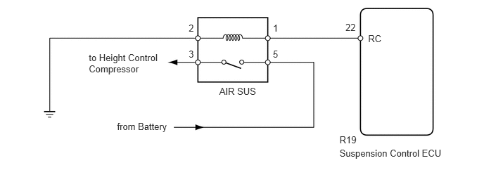
CAUTION / NOTICE / HINT
- NOTICE:
-
When replacing the suspension control ECU, perform registration (See page Suspension>SUSPENSION CONTROL>AIR SUSPENSION SYSTEM>REGISTRATION).
- HINT:
-
If DTC C1782 is output at the same time as C1751, perform the inspection necessary for DTC C1782 first (See page Suspension>SUSPENSION CONTROL>AIR SUSPENSION SYSTEM>C1782).
PROCEDURE
Turn the ignition switch off.
Connect the GTS to the DLC3.
Turn the ignition switch to ON.
Turn the GTS on.
Enter the following menus: Chassis / Air suspension / Active Test.
| Tester Display | Test Part | Control Range | Diagnostic Note |
|---|---|---|---|
| Compressor Motor Relay | AIR SUS relay | ON or OFF | ·
The operating sound of the motor can be heard. ·
When the Active Test is performed, Motor Relay in the Data List changes between ON and OFF accordingly. |
- OK:
Operation of motor can be heard.
| Result | Proceed to |
|---|---|
| NG | A |
| OK (When troubleshooting according to problem symptoms table) | B |
| OK (When troubleshooting according to DTC chart) | C |
A
B
C
(See pageGeneral>INTRODUCTION>HOW TO TROUBLESHOOT ECU CONTROLLED SYSTEMS>HOW TO PROCEED WITH TROUBLESHOOTING)
Turn the ignition switch off.
Remove the AIR SUS relay from the engine room relay block.
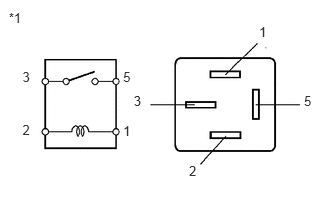
Measure the resistance according to the value(s) in the table below.
- Standard Resistance:
Tester Connection Condition Specified Condition 3 - 5 12 V battery voltage is not applied to terminal 1 and 2 10 kΩ or higher 12 V battery voltage is applied to terminal 1 and 2 Below 1 Ω
| *1 | AIR SUS Relay |
OK
NG
Disconnect the R19 suspension control ECU connector.
Remove the AIR SUS relay from the engine room relay block.
Measure the resistance according to the value(s) in the table below.
- Standard Resistance:
Tester Connection Condition Specified Condition R19-22 (RC) - Engine room relay block AIR SUS relay terminal 1 Always Below 1 Ω R19-22 (RC) - Body ground Always 10 kΩ or higher Engine room relay block AIR SUS relay terminal 2 - Body ground Always Below 1 Ω
OK
NG