1GD-FTV EMISSION CONTROL EXHAUST GAS TEMPERATURE SENSOR(for Front) INSTALLATION
PROCEDURE

 89425
1.INSTALL EXHAUST GAS TEMPERATURE SENSOR
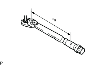
Using a 14 mm union nut wrench, install the No. 3 exhaust gas temperature sensor to the exhaust manifold converter sub-assembly.
- Torque:
Specified tightening torque
30 N*m {306 kgf*cm, 22 ft.*lbf}
| *a | Torque Wrench Fulcrum Length |
- NOTICE:
- ·
If the No. 3 exhaust gas temperature sensor is dropped, replace the new one.
·When reusing the No. 3 exhaust gas temperature sensors, clean the screws and apply anti-seize compound before installing the No. 3 exhaust gas temperature sensor.
- HINT:
- ·
The connector color of the No. 3 exhaust gas temperature sensor is gray.
·Calculate the torque wrench reading when changing the fulcrum length of the torque wrench (See page General>INTRODUCTION>REPAIR INSTRUCTION>PRECAUTION).
·When using a union nut wrench (fulcrum length of 25 mm (0.984 in.)) + torque wrench (fulcrum length of 180 mm (7.09 in.)): 26 N*m (268 kgf*cm, 19 ft.*lbf)
Using a 14 mm union nut wrench, install the No. 2 exhaust gas temperature sensor to the exhaust manifold converter sub-assembly.
- Torque:
Specified tightening torque
30 N*m {306 kgf*cm, 22 ft.*lbf}
| *a | Torque Wrench Fulcrum Length |
- NOTICE:
- ·
If the No. 2 exhaust gas temperature sensor is dropped, replace the new one.
·When reusing the No. 2 exhaust gas temperature sensors, clean the screws and apply anti-seize compound before installing the No. 2 exhaust gas temperature sensor.
- HINT:
- ·
The connector color of the No. 2 exhaust gas temperature sensor is black.
·Calculate the torque wrench reading when changing the fulcrum length of the torque wrench (See page General>INTRODUCTION>REPAIR INSTRUCTION>PRECAUTION).
·When using a union nut wrench (fulcrum length of 25 mm (0.984 in.)) + torque wrench (fulcrum length of 180 mm (7.09 in.)): 26 N*m (268 kgf*cm, 19 ft.*lbf)
Using a 14 mm union nut wrench, install the exhaust gas temperature sensor to the exhaust manifold converter sub-assembly.
- Torque:
Specified tightening torque
30 N*m {306 kgf*cm, 22 ft.*lbf}
| *a | Torque Wrench Fulcrum Length |
- NOTICE:
- ·
If the No. 3 exhaust gas temperature sensor is dropped, replace the new one.
·When reusing the exhaust gas temperature sensors, clean the screws and apply anti-seize compound before installing the exhaust gas temperature sensor.
- HINT:
- ·
The connector color of the exhaust gas temperature sensor is white.
·Calculate the torque wrench reading when changing the fulcrum length of the torque wrench (See page General>INTRODUCTION>REPAIR INSTRUCTION>PRECAUTION).
·When using a union nut wrench (fulcrum length of 25 mm (0.984 in.)) + torque wrench (fulcrum length of 180 mm (7.09 in.)): 26 N*m (268 kgf*cm, 19 ft.*lbf)
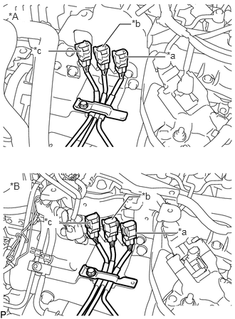
| *A | w/o Urea SCR System |
| *B | w/ Urea SCR System |
| *a | White |
| *b | Black |
| *c | Gray |
Attach the 3 colored connectors to the pipe clamp in the positions shown in the illustration.
Close the clamp of the pipe clamp, and install the bolt.
- Torque:
- 10 N*m (102 kgf*cm, 7 ft.*lbf)
- NOTICE:
-
Arrange the exhaust gas temperature sensor wires so that they do not contact each other.
Connect the No. 3 exhaust gas temperature sensor to the No. 1 vacuum pipe.
- Torque:
- 10 N*m (102 kgf*cm, 7 ft.*lbf)
Connect the 3 connectors to the 3 exhaust gas temperature sensor.
w/ Urea SCR System:
Connect the engine wire to the engine cover bracket with the bolt.
- Torque:
- 8.0 N*m (82 kgf*cm, 71 in.*lbf)
17940D
2.INSTALL INTERCOOLER ASSEMBLY (w/ Urea SCR System)
12601B
3.INSTALL NO. 1 ENGINE COVER SUB-ASSEMBLY (w/o Urea SCR System)
4.ADD ENGINE COOLANT (w/ Urea SCR System)
5.INSPECT FOR COOLANT LEAK (w/ Urea SCR System)