5L-E COOLING WATER PUMP INSTALLATION
PROCEDURE

 16100
1.INSTALL WATER PUMP ASSEMBLY
Install a new gasket, the water pump and tension spring bracket with the 6 bolts.
- Torque:
- 23 N*m (236 kgf*cm, 17 ft.*lbf)
13568
2.INSTALL TIMING BELT
Install the timing belt (See page Engine / Hybrid System>5L-E (ENGINE MECHANICAL)>TIMING BELT>INSTALLATION).
88440D
3.INSTALL NO. 2 IDLE PULLEY ASSEMBLY
4.CONNECT COMPRESSOR AND MAGNETIC CLUTCH
16711
5.INSTALL FAN SHROUD
Install the fan pulley to the water pump.
Install the shroud together with the coupling fan between the radiator and engine.
- NOTICE:
-
Be careful not to damage the radiator core.
Temporarily install the fluid coupling fan to the fan pulley with the 4 nuts. Tighten the nuts as much as possible by hand.
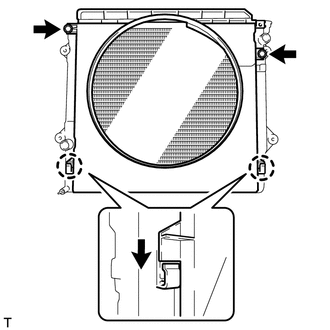
Attach the claws of the shroud as shown in the illustration.
Install the shroud with the 2 bolts.
- Torque:
- 5.0 N*m (51 kgf*cm, 44 in.*lbf)
Install the fan and generator V belt and vane pump V belt (See page Engine / Hybrid System>5L-E (ENGINE MECHANICAL)>DRIVE BELT>INSTALLATION).
Tighten the 4 nuts of the fluid coupling fan.
- Torque:
- 19 N*m (189 kgf*cm, 14 ft.*lbf)
16470
6.INSTALL RADIATOR RESERVOIR
Install the radiator reservoir with the 3 bolts.
- Torque:
- 5.0 N*m (51 kgf*cm, 44 in.*lbf)
Connect the radiator reservoir hose to the radiator tank side.
16572D
7.INSTALL NO. 2 RADIATOR HOSE
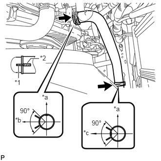
Install the radiator hose.
| *a | Upper |
| *b | Front Side of Vehicle |
| *c | LH Side |
| *1 | Protrusion |
| *2 | Paint Mark |
- HINT:
-
Position the hose clamps as shown in the illustration.
16571C
8.INSTALL NO. 1 RADIATOR HOSE
Install the hose clamp with the 2 nuts.
- Torque:
- 8.5 N*m (87 kgf*cm, 75 in.*lbf)
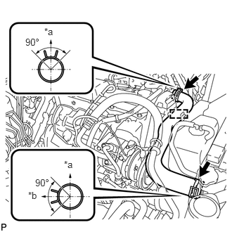
Install the radiator hose.
| *a | Upper |
| *b | RH Side |
- HINT:
-
Position the hose clamps as shown in the illustration.
9.INSTALL RESONATOR WITH AIR CLEANER CAP
28800
10.CONNECT CABLE TO NEGATIVE BATTERY TERMINAL
Click hereGeneral>SETUP>WHEN DISCONNECTING OR RECONNECTING BATTERY TERMINAL>WORK PROCEDURE
- HINT:
-
When disconnecting and reconnecting the battery, there is an automatic learning function that completes learning when the respective system is used.
-
Click hereGeneral>SETUP>WHEN DISCONNECTING OR RECONNECTING BATTERY TERMINAL>AUTOMATIC LEARNING CHART
11.ADD ENGINE COOLANT
12.INSPECT FOR ENGINE COOLANT LEAK
51450
13.INSTALL REAR ENGINE UNDER COVER ASSEMBLY
51405A
14.INSTALL NO. 1 ENGINE UNDER COVER SUB-ASSEMBLY
52129B
15.INSTALL FRONT BUMPER COVER LOWER
53292A
16.INSTALL UPPER RADIATOR SUPPORT SEAL