TELEMATICS TELEMATICS TRANSCEIVER REMOVAL
PROCEDURE

 1. PRECAUTION
- NOTICE:
-
After turning the ignition switch off, waiting time may be required before disconnecting the cable from the negative (-) battery terminal.
-
Click hereGeneral>INTRODUCTION>REPAIR INSTRUCTION>PRECAUTION
2.DISCONNECT CABLE FROM NEGATIVE BATTERY TERMINAL
67910
3.REMOVE DOOR SCUFF PLATE ASSEMBLY RH
62111C
4.REMOVE COWL SIDE TRIM BOARD RH
55317A
5.REMOVE INSTRUMENT SIDE PANEL RH
55607
6.REMOVE NO. 2 INSTRUMENT PANEL UNDER COVER SUB-ASSEMBLY
55461A
7.REMOVE INSTRUMENT PANEL ORNAMENT
55550
8.REMOVE GLOVE COMPARTMENT DOOR ASSEMBLY
85970A
9.REMOVE DOUBLE LOCK DOOR CONTROL RELAY ASSEMBLY (w/ Double Locking System)
10.REMOVE TELEPHONE TRANSCEIVER ASSEMBLY WITH BRACKET
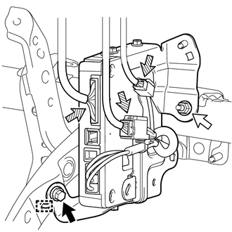

|
Bolt |

|
Nut |

|
Connector |
Remove the bolt and nut.
Detach the guide and remove the telematics transceiver with bracket from the vehicle.
Disconnect the 3 connectors.
86705
11.REMOVE TELEPHONE ANTENNA CORD SUB-ASSEMBLY
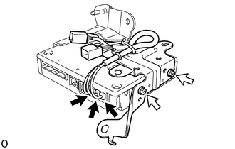
|
|
Connector |
|
|
Screw |
Disconnect the 3 connectors.
Remove the 2 screws and telephone antenna cord sub-assembly.
86719
12.REMOVE TELEPHONE BRACKET
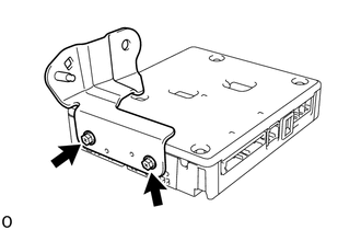
Remove the 2 screws and telephone bracket.
86740
13.REMOVE TELEPHONE TRANSCEIVER ASSEMBLY